Uniform gas flow distribution device of pulverized coal gasification burner

A technology of uniform air distribution and flow guide device, which is applied in the direction of granular/powdered fuel gasification, gasification process, petroleum industry, etc. It can solve the problems of furnace overheating, partial burning, etc., and achieve the elimination of violent disturbance and small pressure loss , the effect of simple structure

Pending Publication Date: 2019-08-02
宝塔国际石化工程技术有限公司
View PDF0 Cites 0 Cited by
  • Summary
  • Abstract
  • Description
  • Claims
  • Application Information

AI Technical Summary

Problems solved by technology

[0003] In order to overcome the deficiencies of the above-mentioned prior art, the object of the present invention is to provide a gas equalizing device that is suitable for non-axial air intake and can effectively realize the uniform distribution of gas along the ring cavity, especially suitable for radial air intake of pulverized coal gasification burners. Oxygen in the gas can realize medium-pressure and large-flow oxygen to be distributed uniformly along the circumference quickly in a short time, and the channel resistance is small. Overheating, partial burning and other problems, improve gasification efficiency

Method used


Image

  • Uniform gas flow distribution device of pulverized coal gasification burner
  • Uniform gas flow distribution device of pulverized coal gasification burner
  • Uniform gas flow distribution device of pulverized coal gasification burner

Examples


Embodiment Construction

[0015] In order to illustrate the present invention more clearly, further description will be made below in conjunction with the accompanying drawings and specific embodiments. The content specifically described below is illustrative rather than restrictive, and should not limit the protection scope of the present invention.

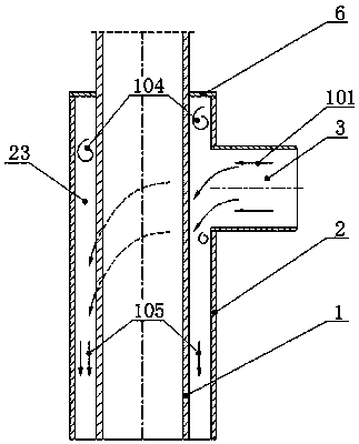
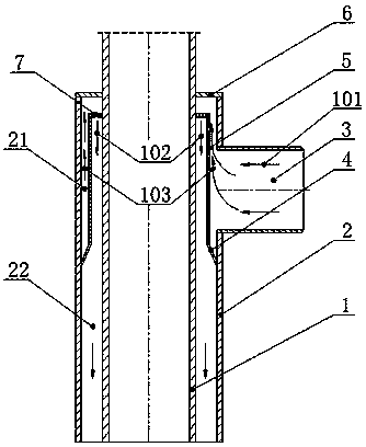
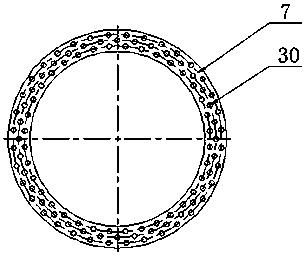
[0016] like Figure 1~3 As shown, the pulverized coal gasification burner gas distribution device provided by the present invention includes at least one air inlet 3 , an inner tube 1 , an outer tube 2 , and a top end cover 6 . A flow guiding device is arranged between the inner tube and the outer tube. The deflector includes a variable diameter tube 4, a deflector ring 5 and an air distribution plate 7, the upper port of the variable diameter tube is connected to the deflector ring, the lower port of the variable diameter tube is fixed on the inner wall of the outer tube, and the inner and outer diameters of the air distribution plate They are respect...


PUM


Abstract

The invention discloses a uniform gas flow distribution device of a pulverized coal gasification burner. The device comprises an inner pipe, an outer pipe, a gas inlet, a top end cover and a flow guide device, wherein the flow guide device consists of a reducer, a flow guide ring and an air distribution plate and is located in an annular cavity formed by the inner pipe and the outer pipe. The flowguide device defines a uniform distribution cavity together with the inner pipe, the top end cover and the upper side of the outer pipe and is communicated with the gas inlet; the flow guide device defines an inner annular cavity together with lower sides of the inner pipe and the outer pipe, the inner annular cavity and the uniform distribution cavity are communicated through vent holes of the air distribution plate, and the lower side of the inner annular cavity is communicated with a follow-up process space. The gas inlet is arranged on the outer pipe and communicated with the uniform distribution cavity. Gas introduced from the gas inlet firstly passes through the uniform distribution cavity and flows reversely after upwards moving to the top end cover, gas flow moves rapidly in the circumferential direction when direction is changed in the cavity, and circumferentially uniform distribution can be basically realzied. Circumferentially uniform distribution of downwards flowing gasis further realized through the air distribution plate, and then, the gas enters the inner annular cavity. Pores formed in the air distribution plate are uniformly distributed to have a rectificationfunction. The device can realize uniform distribution of radially entering gas along the circumferential annular cavity and is simple in structure and low in cost, and the pressure loss of the whole device is smaller.

Description

technical field [0001] The invention relates to the technical field of gas uniform distribution, in particular to the uniform gas flow distribution of an oxygen path of a pulverized coal gasification burner. Background technique [0002] The gasification burner is an important part of the coal gasification device. At present, some of the gasification furnaces in operation in my country have uneven furnace temperature, and even local temperature overheating, which seriously affects the stable operation and service life of the gasification furnace. After analysis, one of the main reasons is that the radially fed oxygen is unevenly distributed in the circumferential direction at the nozzle of the gasification burner, which makes local excess oxygen, violent combustion reaction, and over-temperature partial burning. For this reason, it is necessary to introduce an air flow uniform distribution device in the oxygen channel. However, the current air flow distribution devices are ...

Claims


Application Information

Patent Timeline
IPC IPC(8): C10J3/50
CPCC10J3/50C10J2300/09
Inventor 刘健高兆葛艳荣
Owner 宝塔国际石化工程技术有限公司
Why Eureka
Try Eureka