Homemade wine brewing jar with filtering function
A wine, home technology
- Summary
- Abstract
- Description
- Claims
- Application Information
AI Technical Summary
Problems solved by technology
Method used
Image

Examples
Embodiment Construction
[0022] The following will clearly and completely describe the technical solutions in the embodiments of the present invention with reference to the accompanying drawings in the embodiments of the present invention. Obviously, the described embodiments are only some, not all, embodiments of the present invention.
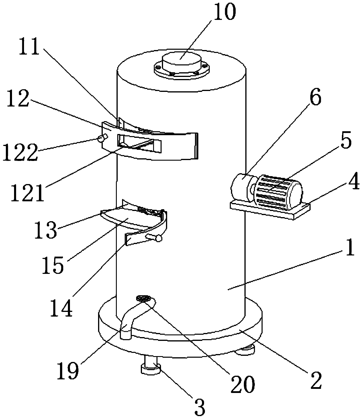
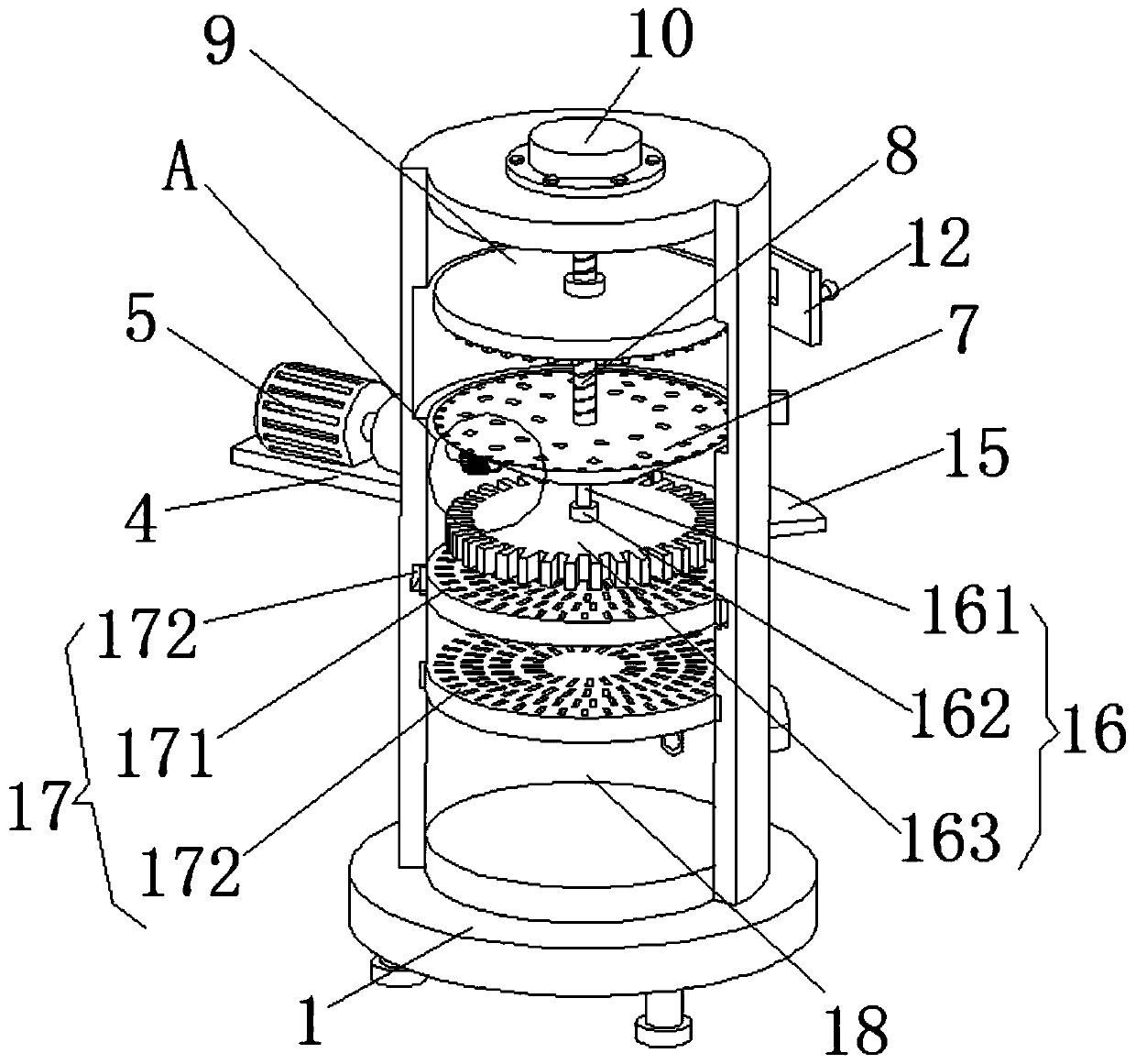
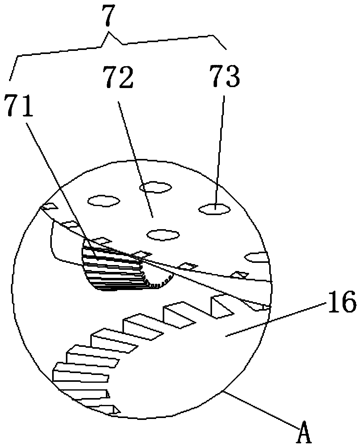
[0023] refer to Figure 1-4 , a home-made wine brewing tank with filtering function, comprising a tank body 1, a base 2 is fixedly installed on the bottom of the tank body 1, a plurality of support feet 3 are fixedly installed on the bottom of the base 2, and the side wall at the top of the tank body 1 is fixed Mounting plate 4 is installed, and the top of mounting plate 4 is fixedly installed with motor 5, and one side of motor 5 is provided with mounting base 6, and mounting base 6 is fixedly connected on tank body 1, and the output shaft of motor 5 runs through mounting base 6 and is always Extending to the inside of the tank body 1, the inside of the tank body 1 ...
PUM
 Abstract
Description
Claims
Application Information