High-rise drainage bend tube

A curved, high-rise technology, applied in the field of pipeline systems, can solve problems such as affecting the work of drainage pipelines, large water flow potential, pipeline rupture, etc., to facilitate regular maintenance and replacement, enhance energy dissipation effect, and prevent impact damage.

Pending Publication Date: 2019-08-02
福建亚通新材料科技股份有限公司
View PDF1 Cites 1 Cited by
  • Summary
  • Abstract
  • Description
  • Claims
  • Application Information

AI Technical Summary

Problems solved by technology

However, in the drainage of high-rise buildings, due to the smooth inner wall of the pipeline, small friction and large potential energy of water flow, it has a great influence on the strength of the pipeline and the stability of drainage.
At present, 4 ordinary drainage pipes with 45° elbows are generally used to reduce the potential energy of water flow, but this method has certain defects: for example, when there are foreign objects such as stones in the drainage pipe that fall with the water flow and have huge potential energy, It is easy to break through the 45° elbow at the turn, causing the pipe to break and fall into the water, affecting the normal operation of the drainage pipe
[0004] However, the following problems still exist: the energy-reducing part is a curve, and the impact force of the water flow with huge potential energy and foreign objects such as mixed stones on the curve remains unchanged. The protection of lining and reinforcement, the risk of bend rupture still exists

Method used


Image

  • High-rise drainage bend tube
  • High-rise drainage bend tube
  • High-rise drainage bend tube

Examples


Embodiment 1

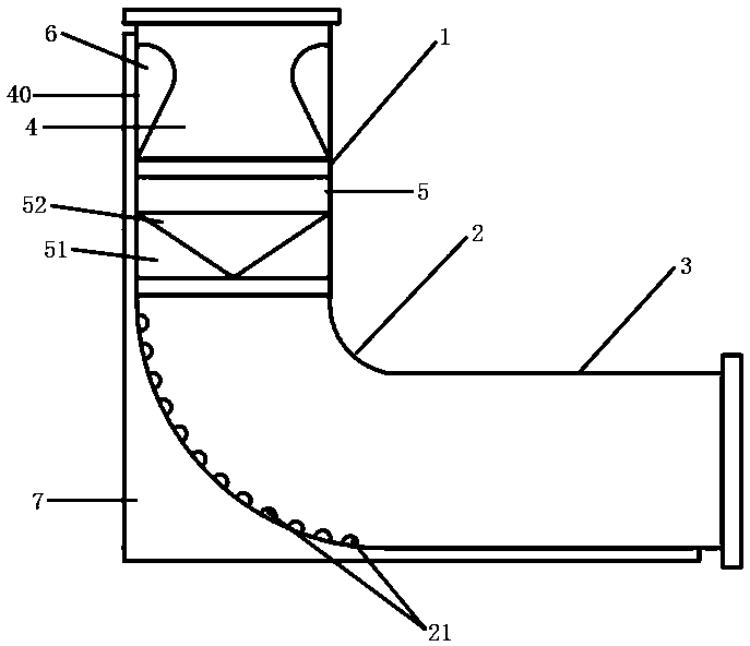
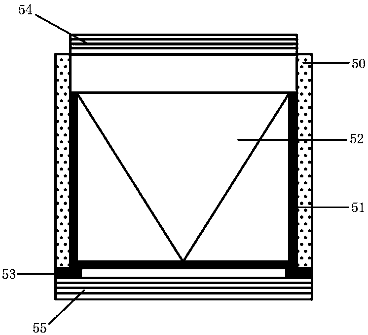
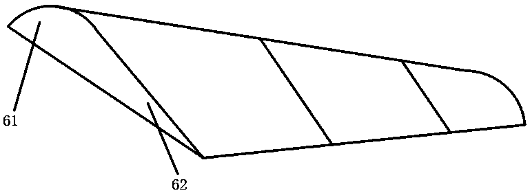
[0028] A high-rise drainage bend pipe, comprising a water inlet section 1, a bend section 2, and a water outlet section 3. The water inlet section is composed of an energy dissipation pipe 4 and a filter pipe 5 detachably connected to the lower end of the energy dissipation pipe; the energy dissipation pipe 4 includes a first The pipe body 40 and the energy dissipator 6 welded on the pipe wall in the first pipe body, the upstream surface of the energy dissipator 6 is a circular arc surface 61, and the back surface is an inclined surface 62, and the upstream surface is smoothly connected with the inclined surface for energy dissipation. The length of the filter is 1 / 4 of the length of the water inlet section, and the number is 2, which are symmetrically distributed on the inner wall of the first pipe; the filter pipe includes a second pipe body 50, an internal thread 54 arranged on the upper end of the second pipe body And the external thread 55 at the lower end of the second pi...

Embodiment 2

[0030] A high-rise drainage bend pipe, comprising a water inlet section 1, a bend section 2, and a water outlet section 3. The water inlet section is composed of an energy dissipation pipe 4 and a filter pipe 5 detachably connected to the lower end of the energy dissipation pipe; the energy dissipation pipe 4 includes a first The pipe body 40 and the energy dissipator 6 bonded to the pipe wall in the first pipe body, the upstream surface of the energy dissipator 6 is an arc surface 61, and the back surface is an inclined surface 62, and the upstream surface is smoothly connected with the inclined surface, forming a Airfoil, the length of the energy dissipator is 1 / 3 of the length of the water inlet section, and the number is 4, which are symmetrically distributed on the water inlet to the inner pipe wall; the filter pipe includes a second pipe body 50, which is arranged on the second pipe body The internal thread 54 at the upper end and the external thread 55 at the lower end o...

Embodiment 3

[0032] A high-rise drainage bend pipe, comprising a water inlet section 1, a bend section 2, and a water outlet section 3. The water inlet section is composed of an energy dissipation pipe 4 and a filter pipe 5 detachably connected to the lower end of the energy dissipation pipe; the energy dissipation pipe 4 includes a first The pipe body 40 and the energy dissipator 6 clamped on the pipe wall in the first pipe body, the upstream surface of the energy dissipator 6 is an arc surface 61, and the back surface is an inclined surface 62, and the upstream surface is smoothly connected with the inclined surface, forming a Airfoil, the length of the energy dissipator is 1 / 4 of the length of the water inlet section, and the number is 3, which are symmetrically distributed on the water inlet to the inner pipe wall; the filter pipe includes a second pipe body 50, which is arranged on the second pipe body The internal thread 54 at the upper end and the external thread 55 at the lower end ...


PUM


Abstract

The utility model discloses a high-rise drainage bend tube which comprises a water inlet section, a bend section and a water outlet section, the water inlet section is detachably connected with the bend section, the water inlet section comprises an energy dissipation tube and a filtering tube which are detachably connected, the energy dissipation tube comprises a first tube body and a plurality ofenergy dissipaters connected to the inner tube wall of the first tube body, and the filtering tube comprises a second tube body, a filtering box connected to the inner tube wall of the second tube body and a conical filtering net arranged in the filtering box. The pipeline is designed to reduce energy of the pipeline before water flow and sundries with huge potential energy impact the bend tube,impact damage to the bend tube is effectively reduced, and the pipeline is easy to replace and maintain, simple, practical and easy to implement.

Description

technical field [0001] The invention belongs to the technical field of piping systems, and in particular relates to a high-rise drainage bend pipe. Background technique [0002] Drainage pipes are mainly responsible for the drainage of rainwater, sewage, farmland irrigation and drainage. Drainage pipes are divided into plastic drainage pipes, concrete drainage pipes and reinforced concrete drainage pipes. Drainage pipes are widely used in drainage fields such as roads, railway subgrades, subway projects, waste landfills, tunnels, green belts, sports fields and slope protection caused by high water content, as well as agricultural, underground irrigation, horticultural drainage systems, etc. And soft permeable pipe, plastic blind ditch has become the three main products in my country's civil engineering construction (water seepage, drainage). Depending on the drainage pressure of the municipal drainage pipe network, double-wall corrugated pipes and straight-wall pipes can be...

Claims


Application Information

Patent Timeline
Patent Type & Authority Applications(China)
IPC IPC(8): E03F3/04E03F5/14
CPCE03F3/04E03F5/14
Inventor 彭伏弟陈文彬陈晓梅吴亚平
Owner 福建亚通新材料科技股份有限公司
Why Eureka
Try Eureka