
Two-way sealing butterfly valve

A two-way sealing and butterfly valve technology, applied in the direction of lift valve, valve details, valve device, etc., can solve the problems of reduced pipeline flow rate, high cost, narrow application range of butterfly valve, etc., and achieve the effect of increasing the sealing specific pressure and good sealing performance

Active Publication Date: 2019-08-02
SHANGHAI HUGONG VALVE FACTORY (GRP) CO LTD
View PDF9 Cites 2 Cited by
  • Summary
  • Abstract
  • Description
  • Claims
  • Application Information

AI Technical Summary

Problems solved by technology

[0002] Butterfly valve is a kind of valve that uses disc type butterfly plate to turn back and forth about 90° to open, close or adjust the flow of medium. friction, the butterfly valve structure generally adopts a metal-to-metal sealing triple eccentric structure, and its disadvantage is that when the working conditions require a two-way sealing function, the butterfly valve with the triple eccentric structure only has good one-way sealing, that is, It is said that if the medium enters the inner cavity of the butterfly valve from the inlet side of the valve, the valve has good sealing performance when it is closed, and if the medium enters the inner cavity of the butterfly valve from the outlet side of the valve, the valve cannot keep sealing. Butterfly valves with triple eccentric structure have a narrow range of use. In order to meet the working conditions of bidirectional sealing function, two butterfly valves of this type can only be installed together, resulting in high cost, cumbersome installation, reduced pipeline flow rate, and increased pipeline pressure drop.

Method used


Image

  • Two-way sealing butterfly valve
  • Two-way sealing butterfly valve

Examples


Embodiment Construction

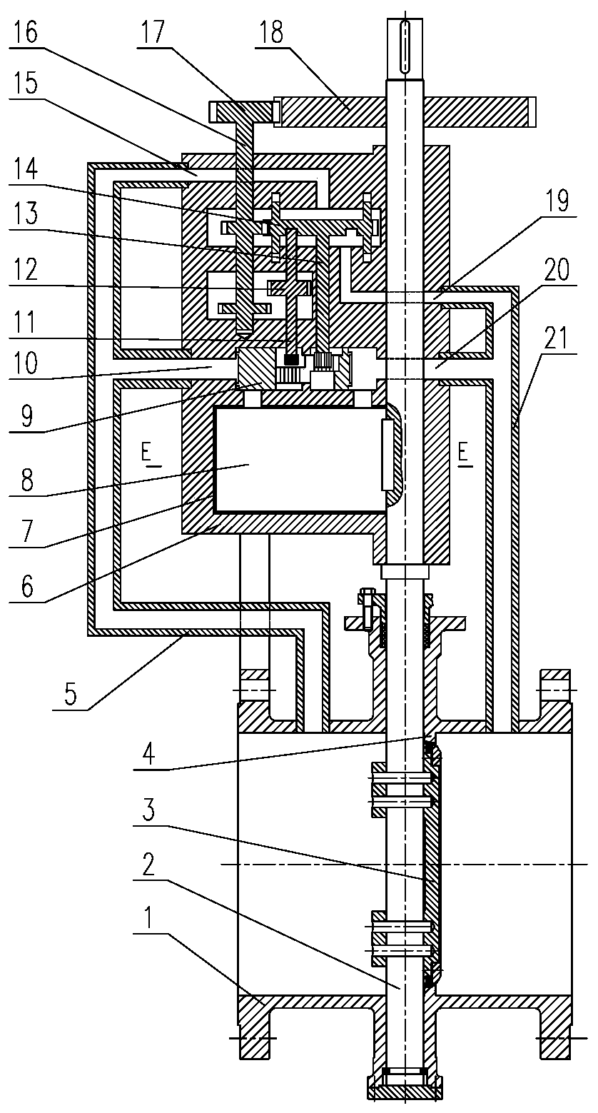
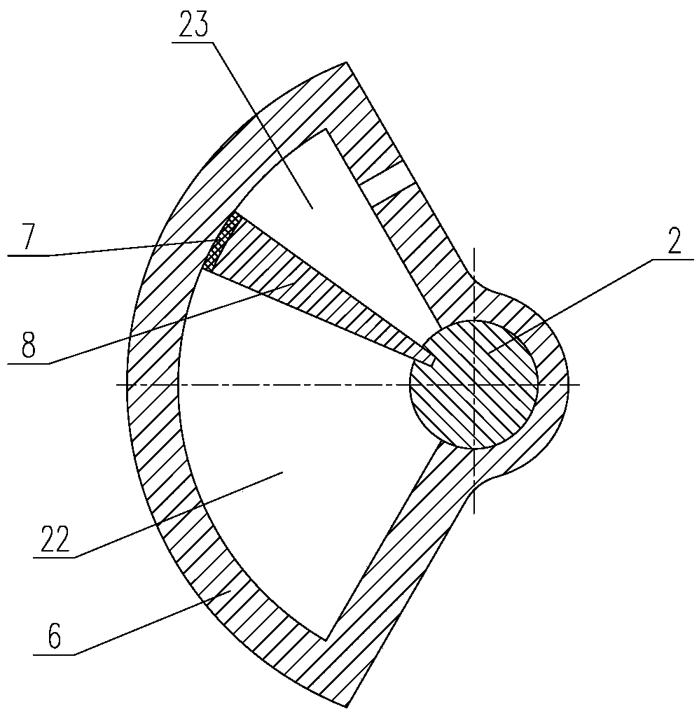
[0011] according to figure 1 , 2 It can be seen that this bidirectional sealing butterfly valve includes: valve body 1, valve stem 2, butterfly plate 3 and valve seat 4, the valve seat 4 is fixedly installed in the inner cavity of the valve body 1, and the inner surface of the valve seat 4 is provided with a seat seal On the surface, the butterfly plate 3 is installed in the inner cavity of the valve body 1, and the outer surface of the butterfly plate 3 is provided with a butterfly plate sealing surface that can form a seal with the sealing surface of the valve seat. The lower end of the valve stem 2 extends downward into the inner cavity of the valve body 1 and is The butterfly plate 3 forms a fixed connection. When the butterfly plate 3 cooperates with the valve seat 2 to form a closed valve, the butterfly plate 3 isolates the inner cavity of the valve body 1 to form a left cavity and a right cavity. The control mechanism, the left inlet connecting pipe 5 and the right inl...


PUM


Abstract

The invention relates to a two-way sealing butterfly valve. The two-way sealing butterfly valve is characterized in that a supercharging device, a medium flow direction control mechanism, a left inletconnecting pipe and a right inlet connecting pipe are further arranged above a valve body, the left inlet connecting pipe communicates with a left cavity, and the right inlet connecting pipe communicates with a right cavity. The supercharging device comprises a supercharging tank, a supercharging plate and a sealing ring, the supercharging tank is internally provided with a control chamber with across section of a fan-shaped structure, the supercharging plate is arranged in the control chamber and divides the control chamber into a supercharging chamber and a breathing chamber, one end of the supercharging plate is fixedly connected with a valve stem, and the breathing chamber communicates with the atmosphere; and through cooperation of the left inlet connecting pipe, the right inlet connecting pipe and the medium flow direction control mechanism, media in the left cavity and the right cavity are controlled to enter the supercharging chamber, the supercharging plate is pushed by themedia in the supercharging cavity to generate acting force acting on a butterfly plate in the butterfly plate closing direction through the valve stem, the butterfly plate and a valve seat keeps sealed, and the advantage of being good in two-way sealing performance is achieved.

Description

technical field [0001] The invention relates to a valve, in particular to a bidirectional sealing butterfly valve. Background technique [0002] Butterfly valve is a kind of valve that uses disc type butterfly plate to turn back and forth about 90° to open, close or adjust the flow of medium. friction, the butterfly valve structure generally adopts a metal-to-metal sealing triple eccentric structure, and its disadvantage is that when the working conditions require a two-way sealing function, the butterfly valve with the triple eccentric structure only has good one-way sealing, that is, It is said that if the medium enters the inner cavity of the butterfly valve from the inlet side of the valve, the valve has good sealing performance when it is closed, and if the medium enters the inner cavity of the butterfly valve from the outlet side of the valve, the valve cannot keep sealing. Butterfly valves with triple eccentric structure have a narrow application range. In order to m...

Claims


Application Information

Patent Timeline
Patent Type & Authority Applications(China)
IPC IPC(8): F16K1/226F16K31/12
CPCF16K1/226F16K31/12
Inventor 徐国华
Owner SHANGHAI HUGONG VALVE FACTORY (GRP) CO LTD
Learn More