Heavy-caliber high-temperature pilot-operated type control valve

A pilot-operated, large-diameter technology, applied in the direction of lift valves, safety valves, balance valves, etc., can solve the problem of low safety release devices for re-closed types, and achieve the effect of improved cost performance, low cost, and perfect manufacturing process

Inactive Publication Date: 2010-06-09
HANGZHOU WORLDWISE VALVE
View PDF0 Cites 2 Cited by
  • Summary
  • Abstract
  • Description
  • Claims
  • Application Information

AI Technical Summary

Problems solved by technology

Due to the lack of a series of test conditions and professional technical personnel in China, the high-performance heavy-closing safety release device has remained at a relatively low level for many years.

Method used


Image

  • Heavy-caliber high-temperature pilot-operated type control valve
  • Heavy-caliber high-temperature pilot-operated type control valve
  • Heavy-caliber high-temperature pilot-operated type control valve

Examples


Embodiment 1

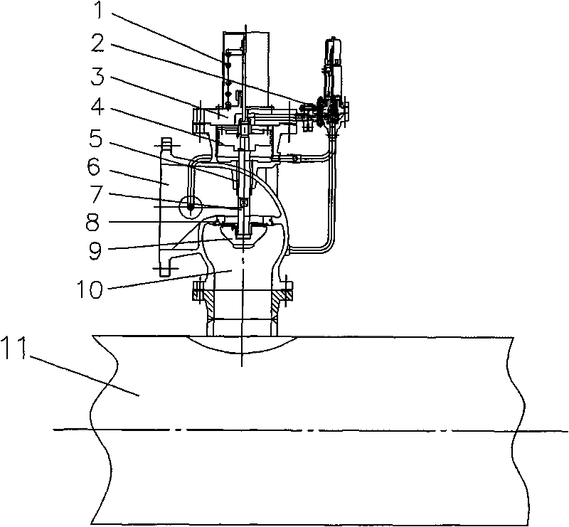
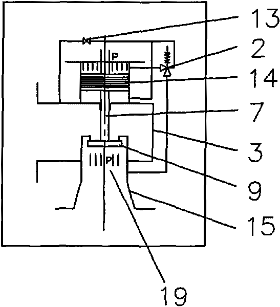
[0021] Example 1, such as Figure 1-4 As shown, this large-diameter high-temperature pilot control valve mainly includes the main control valve 3, the auxiliary pilot valve 2 and the pressure-bearing equipment 11, the main control valve 3 is connected with the auxiliary pilot valve 2, and the auxiliary pilot valve 2 passes through the bypass pipe The passage 12 communicates with the outlet port 6 of the main control valve 3, the bypass pipe 12 is provided with a check valve 13, the bottom of the main control valve 3 is provided with a nozzle 15, the nozzle 15 forms an inlet chamber 10, and the inlet chamber 10 is connected to the pressure-bearing The device 11 is connected and fixed. The main control valve 3 mainly includes a valve seat 8, a valve stem 7, a valve disc 9, a movable component and a guide sleeve 5, the valve seat 8 is provided with a valve stem 7, and the lower end of the valve stem 7 is provided with a valve disc 9, and the valve disc 9 is located at the lower ...

Embodiment 2

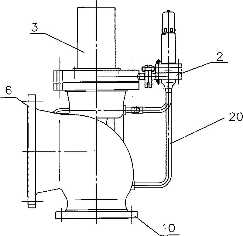
[0022] Example 2, such as Figure 5-8 As shown, the main structure is the same as that of Embodiment 1, the outlet chamber 6 of the main control valve 3 is connected to the evaporator 16 , and the secondary pilot valve 2 communicates with the evaporator 16 through the main pipeline 20 . The structure at this time forms a pressure-temperature control valve. The bearing pressure 19 of the inlet chamber 10, the discharge signal 18 of the outlet chamber 6, and the control signal 17 generated by the evaporator 16 are all transmitted to the auxiliary pilot valve 2, thereby affecting the operation of the main control valve 3. operate. The difference between the inlet pressure of the main valve and the control pressure of the pilot valve is not more than 2.5 MPa, and the opening of the valve is realized by using the area difference between the piston chamber of the main valve and the disc 9 of the main valve.

[0023] The present invention utilizes the medium pressure in the pressure...


PUM


Abstract

The invention relates to a heavy-caliber high-temperature pilot-operated type control valve. The control valve mainly comprises a main control valve, an auxiliary pilot valve and compression equipment, wherein the main control valve is communicated with the auxiliary pilot valve; the auxiliary valve is communicated with an outlet cavity of the main control valve through a bypass pipeline; the bottom of the main control valve is provided with a nozzle which forms an inlet cavity; and the inlet cavity is connected and fixed with the compression equipment. The control valve has the advantages that a sealing pair structure combined by an inverse valve clack and a valve seat effectively improves the seal specific pressure of high temperature working conditions, and ensures that the device is in a reliable sealing state before startup. Because the device is under the high temperature working conditions in running and acting processes, research and development on the structure of a movable part adopts a labyrinth piston ring which is made of a metal material and is arranged between a piston and a cylinder liner, and solves the problems of movability, friction and leakage of the structure in a high-temperature medium.

Description

technical field [0001] The invention mainly relates to the field of control valves on pressure vessels and pressure pipelines, and is mainly a large-diameter high-temperature pilot control valve. Background technique [0002] With the continuous development of energy saving, emission reduction and reuse of energy in the electric power industry, large-diameter high-temperature pilot control valves equipped on pressure-bearing equipment in electric power and petrochemical industries have become more and more common. Since the device is in the overpressure protection working condition of high-temperature medium, the system pressure exceeds the limit and recovery needs to be started and shut down. At the same time, the safe operation of the system and the loss of control energy must also be considered. In order to meet the development and demand of overpressure protection for pressure equipment, it is of far-reaching significance to develop energy-saving products of large-diamet...

Claims


Application Information

Patent Timeline
IPC IPC(8): F16K17/36F16K1/00F16K1/32
Inventor 陈立龙张明陈荣斌钱新华罗鸣陈英俊郑书斌朱杭钱
Owner HANGZHOU WORLDWISE VALVE
Why Eureka
Try Eureka