
An electromagnetic heating device and its control method

A technology of electromagnetic heating device and control method, applied in induction heating device, control system, induction heating and other directions, can solve the problems of air pollution, long conveying pipeline, frequent maintenance, etc., and achieve the effect of high intelligence and avoid pipe bursting

Active Publication Date: 2020-09-22
WENZHOU SUNSHINE MACHINERY TECH
View PDF5 Cites 0 Cited by
  • Summary
  • Abstract
  • Description
  • Claims
  • Application Information

AI Technical Summary

Problems solved by technology

At present, most of the steam generators used in industrial workshops are boilers, which generate heat by burning coal or natural gas to heat water to generate steam. This method requires a dedicated boiler room, which occupies a large area, and fuel combustion will generate A large amount of harmful polluting gas
[0003] Specific to the existing industrial fields, such as the paper industry, large equipment requires a large amount of steam heating, and a steam boiler using a combustion medium must be added. Since the boiler is a special equipment, it needs to be operated and maintained by professionals and needs to be far away from the production area, so it is necessary to lay Longer pipelines lead to high costs, and at the same time, long-distance pipelines bring large transmission losses. In addition, there are air pollution and PM2.5 emissions problems due to the use of combustion media
Larger boilers must also add environmental protection devices such as dust removal and flue gas desulfurization, and require frequent maintenance to ensure the effectiveness of the equipment, and the maintenance cost is relatively high
Moreover, the working characteristics of the boiler determine that it responds slowly to the steam demand of the equipment, and cannot be connected with the equipment control system, so it needs to be improved

Method used


Image

  • An electromagnetic heating device and its control method
  • An electromagnetic heating device and its control method
  • An electromagnetic heating device and its control method

Examples


Embodiment Construction

[0034] The present invention will be further described with reference to the accompanying drawings.

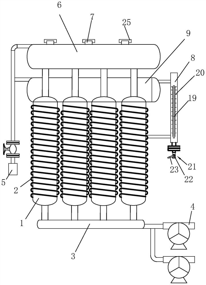
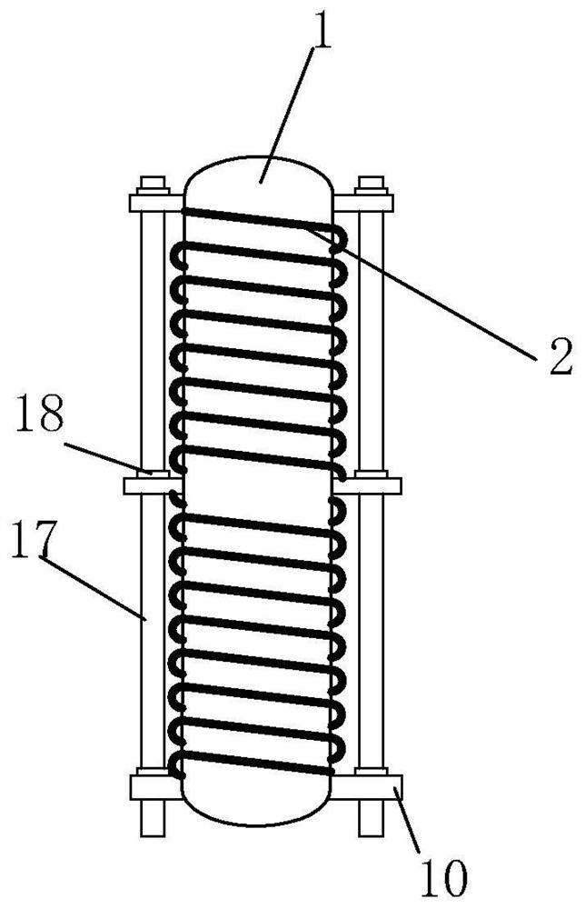
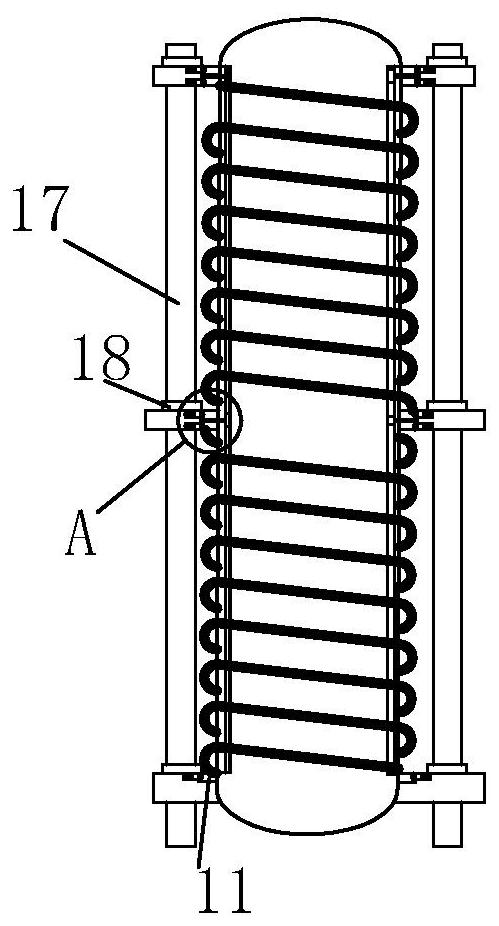
[0035] An electromagnetic heating device such as figure 1 , figure 2 , image 3 , Figure 4 and Figure 5As shown, it includes a plurality of tube bodies 1, and the tube bodies 1 are arranged in a cylindrical shape, and an electromagnetic heat generator is sheathed on the outside of each of the tube bodies 1, and the electromagnetic generator is used to heat the liquid in the tube body 1. The electromagnetic heat generator includes an electromagnetic induction coil tube 2 sleeved on the outside of the tube body 1. When the electromagnetic induction coil tube 2 is energized, the electromagnetic induction coil tube 2 heats the liquid in the tube body 1. The bottoms of the multiple pipe bodies 1 are connected to the same first water inlet pipe 3, one end of the first water inlet pipe 3 is connected to two first water pumps 4, and the top of the first water inlet pipe 3 is co...


PUM


Abstract

The invention relates to an electromagnetic heating device and a control method thereof. The electromagnetic heating device comprises a plurality of pipe bodies. Each pipe body is sleeved with an electromagnetic heat generator which comprises an electromagnetic induction coil pipe arranged outside the pipe body in a sleeving mode. The bottoms of the pipe bodies communicate with a first water inletpipe. One end of the first water inlet pipe is connected with two first water pumps. The top of the first water inlet pipe is connected with a water outlet pipe. A plurality of steam outlets are formed in the side, away from the first water inlet pipe, of the water outlet pipe. The pipe bodies are connected with a connecting pipe. The other end of the connecting pipe is connected with a second water inlet pipe. The end, away from the connecting pipe, of the second water inlet pipe is connected with a second water pump. The electromagnetic heating device has the advantages of being environmentally friendly, high in efficiency and low in maintenance cost.

Description

technical field [0001] The invention relates to the technical field of steam heating equipment, in particular to an electromagnetic heating device and a control method thereof. Background technique [0002] Steam generators, commonly used equipment such as boilers, are mechanical devices that use the heat energy of fuel or other energy sources to heat water into hot water or steam. At present, most of the steam generators used in industrial workshops are boilers, which generate heat by burning coal or natural gas to heat water to generate steam. This method requires a dedicated boiler room, which occupies a large area, and fuel combustion will generate Large quantities of harmful polluting vapours. [0003] Specific to the existing industrial fields, such as the paper industry, large equipment requires a large amount of steam heating, and a steam boiler using a combustion medium must be added. Since the boiler is a special equipment, it needs to be operated and maintained b...

Claims


Application Information

Patent Timeline
Patent Type & Authority Patents(China)
IPC IPC(8): F22B1/28F22B35/00H05B6/02H05B6/10H05B6/36
CPCF22B1/28F22B35/00H05B6/02H05B6/10H05B6/36
Inventor 章方国王健王汝鸣章晋睿
Owner WENZHOU SUNSHINE MACHINERY TECH
Learn More