Waste heat recovery system

A waste heat recovery system and heat exchanger technology, applied in the direction of heat exchangers, indirect heat exchangers, heat exchanger types, etc., can solve the problem of waste heat waste, etc., to improve efficiency, facilitate access, and improve heat insulation effect. Effect

Active Publication Date: 2020-08-25
重庆岩昱节能科技有限公司
View PDF11 Cites 1 Cited by
  • Summary
  • Abstract
  • Description
  • Claims
  • Application Information

AI Technical Summary

Problems solved by technology

[0004] The invention provides a waste heat recovery system, which solves the problem of waste heat caused by natural cooling of high-temperature workpieces in the prior art

Method used


Image

  • Waste heat recovery system
  • Waste heat recovery system
  • Waste heat recovery system

Examples


Embodiment 1

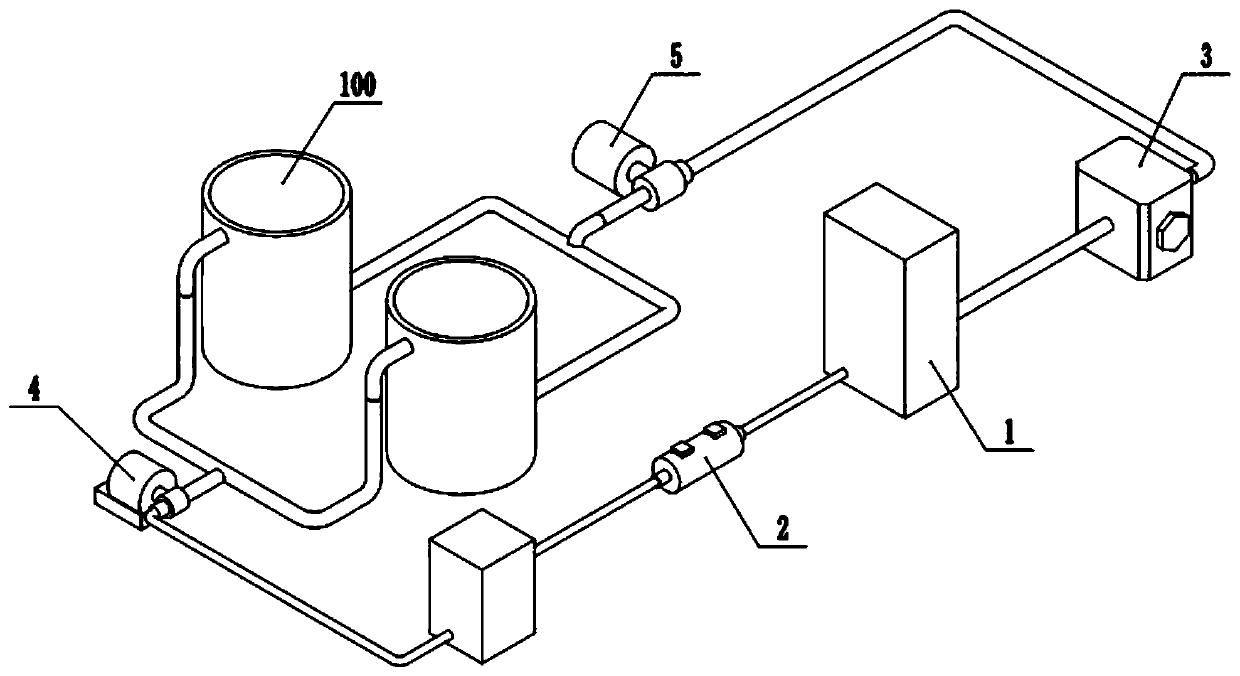
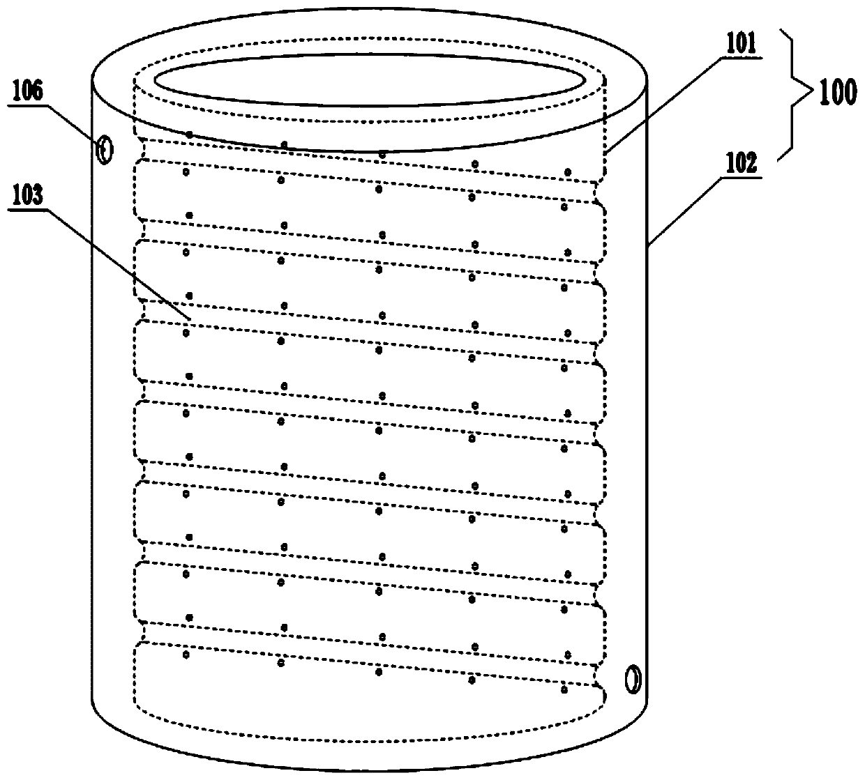
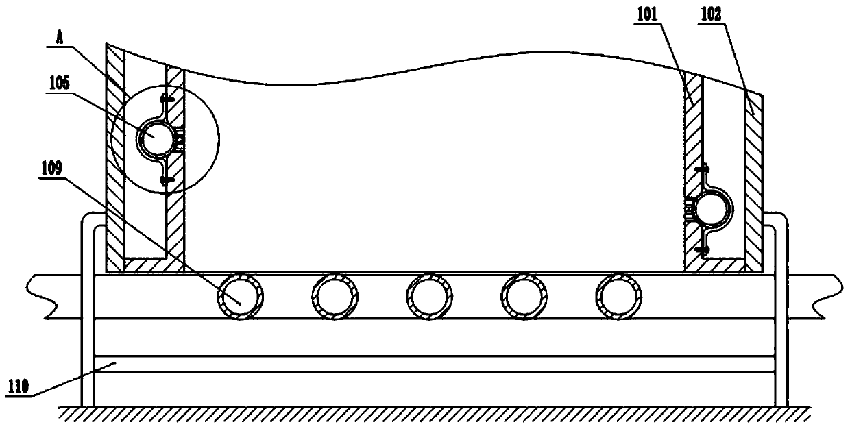
[0036] Embodiment one is basically as attached figure 1 , figure 2 and image 3 Shown:

[0037] The waste heat recovery system includes recovery components, circulation pump, liquid storage tank 1, heat exchanger 2 and heater 3, which are sequentially connected through pipelines. The above mechanisms are all fixed by the frame, and the circulation pump includes a mechanical pump 4 and an electromagnetic pump 5. The recovery assembly includes a heat-absorbing cylinder 100 vertically fixed on the frame. The heat-absorbing cylinder 100 is a sandwich structure, specifically including an inner cylinder 101 and an outer cylinder 102. The inner cylinder 101 and the outer cylinder 102 are fixedly arranged, and the inner and outer cylinders 102 forms a closed heat exchange channel at the upper and lower ends, combined with figure 1 As shown, the heat exchange channel on the heat absorbing cylinder 100, the mechanical pump 4, the liquid storage tank 1, the heat exchanger 2, the heat...

Embodiment 2

[0046] The difference between embodiment two and embodiment one is:

[0047] Such as Figure 6 As shown, at the bottom of the top cover 200, there are a plurality of heat conduction units evenly distributed along the protrusion 201, and the heat conduction units are used to dissipate the heat at the bottom of the top cover 200 to the heat absorption pipe 105, wherein the heat conduction unit includes a heat conduction plate 300 and a drive The drive mechanism for the heat conduction plate 300 to swing back and forth around the horizontal axis. The heat conduction plate 300 is located between the protrusion 201 and the inner cylinder 101. In this embodiment, the drive mechanism includes a geared motor 301 and a guide rod 302. The geared motor 301 is fixed on the top cover 200 and the top cover 200 is provided with a shaft hole for the output shaft of the geared motor 301 to pass through. On the drive shaft of the geared motor 301, an incomplete gear 304 located below the top co...


PUM


Abstract

The invention relates to the technical field of cooling industrial equipment, and particularly discloses a waste heat recovery system. The system comprises a recovery assembly, a circulating pump, a liquid storage tank and a heat exchanger which communicate in sequence, wherein the recovery assembly comprises vertically-arranged heat absorption barrels, the heat absorption barrels comprise inner barrels and outer barrels, channels for allowing a heat exchange medium to flow are formed between the inner barrels and the outer barrels, the tops of the heat absorption barrels are provided with topcovers which cover the heat absorption barrels, and the centers of the bottoms of the top covers are protrusions in an inverted cone shape. By adopting the technical scheme, the problem of waste of waste heat caused by natural cooling of a high-temperature workpiece in the prior art is solved.

Description

technical field [0001] The invention relates to the technical field of cooling industrial equipment, in particular to a waste heat recovery system. Background technique [0002] Waste heat refers to the unutilized heat energy generated by various heat energy conversion equipment, energy-consuming equipment, chemical reaction equipment and high-temperature workpieces in the production process. In textile printing and dyeing, electroplating processing, chemical and pharmaceutical, printing drying, coal slime drying, casting, electrolytic aluminum production and other industrial fields, there is a large amount of waste heat that needs to be recycled. If this part of energy can be fully utilized through recycling, it will greatly reduce industrial energy loss, and waste heat recovery is an important way to improve economy and save fuel. [0003] For the cooling of high-temperature workpieces, most manufacturers usually stack high-temperature workpieces in a certain area, and th...

Claims


Application Information

Patent Timeline
Patent Type & Authority Patents(China)
IPC IPC(8): F28D21/00F28F9/00
CPCF28D21/0001F28F9/001
Inventor 黎泽洪杨帆
Owner 重庆岩昱节能科技有限公司
Why Eureka
Try Eureka