
Eyeball tracking device and eyeball tracking equipment

A technology of eye tracking and mounting frame, which is applied in the field of smart wearables, can solve problems such as ambient light interference, and achieve the effect of reducing interference

Pending Publication Date: 2019-08-02
北京七鑫易维科技有限公司 +1
View PDF0 Cites 3 Cited by
  • Summary
  • Abstract
  • Description
  • Claims
  • Application Information

AI Technical Summary

Problems solved by technology

[0004] The first object of the present invention is to provide an eye tracking device to improve the problem that the existing eye tracking device based on the pupil-corneal reflection method is easily interfered by ambient light

Method used


Image

  • Eyeball tracking device and eyeball tracking equipment
  • Eyeball tracking device and eyeball tracking equipment
  • Eyeball tracking device and eyeball tracking equipment

Examples


Embodiment Construction

[0050] The present invention will be further described in detail below with reference to the drawings and embodiments. It can be understood that the specific embodiments described here are only used to explain the present invention, but not to limit the present invention. In addition, it should be noted that, for ease of description, the drawings only show part of the structure related to the present invention, but not all of the structure.

[0051] In the description of the present invention, unless otherwise clearly specified and limited, the terms "connected", "connected", and "fixed" should be interpreted broadly, for example, they may be fixedly connected, detachably connected, or integrated ; It can be a mechanical connection or an electrical connection; it can be directly connected or indirectly connected through an intermediate medium, and it can be the internal communication between two components or the interaction relationship between two components. For those of ordi...


PUM


Abstract

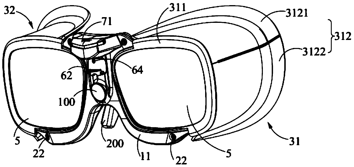
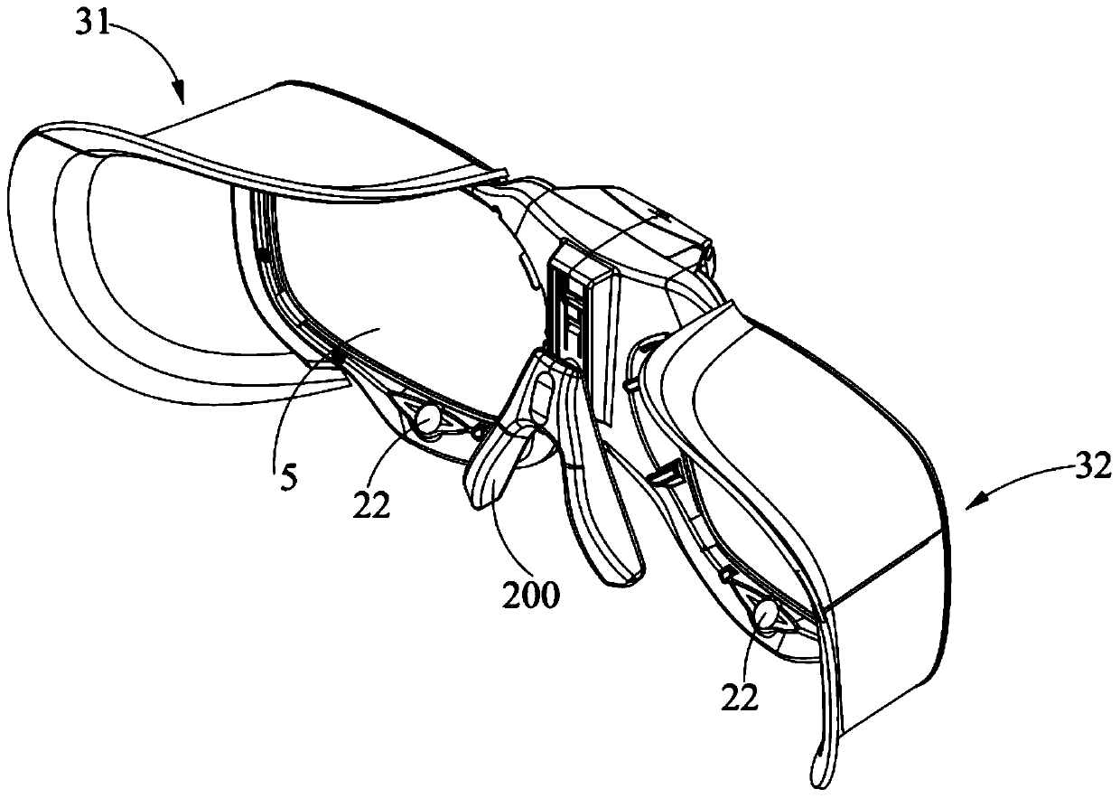
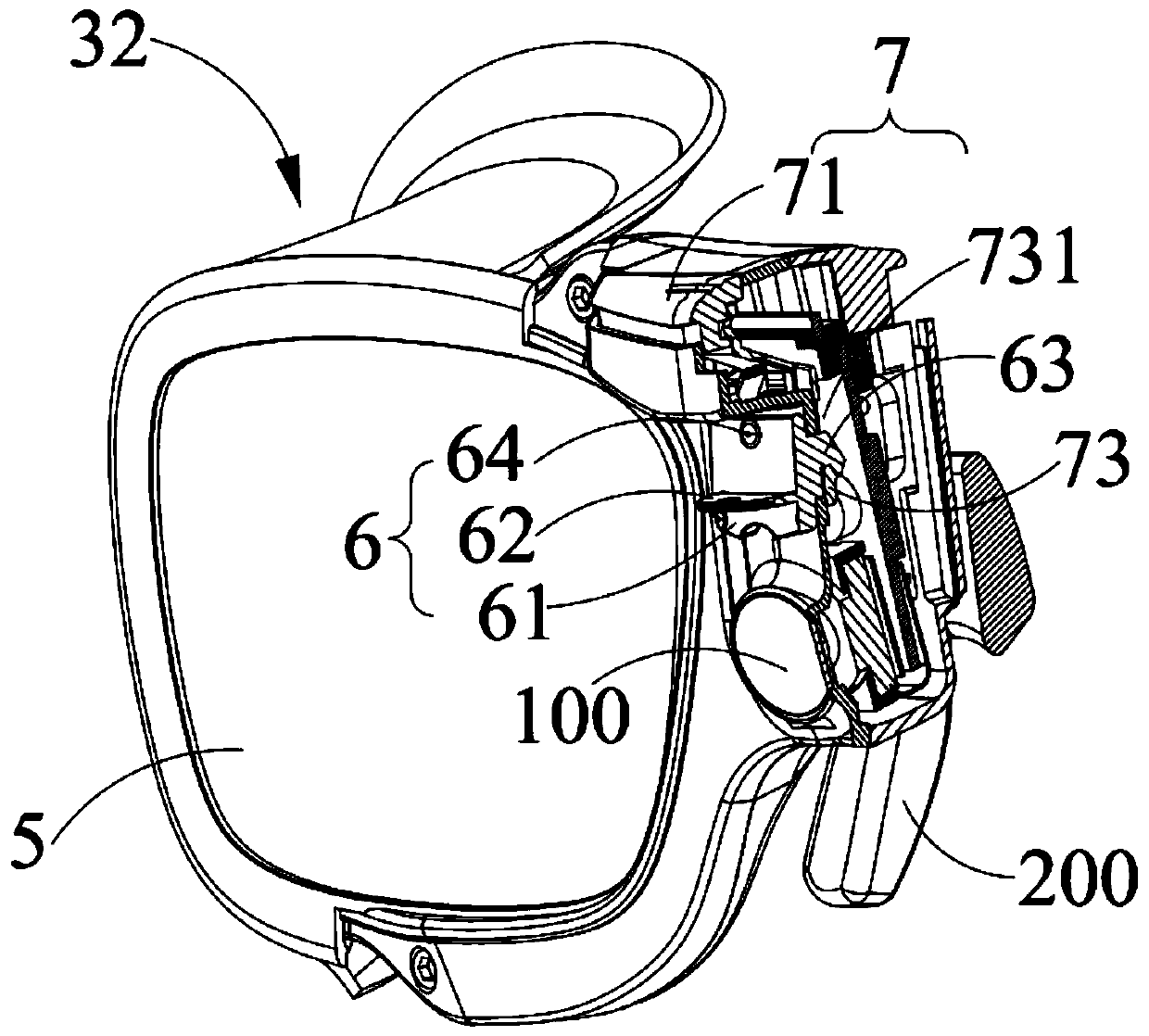
The invention belongs to the technical field of intelligent wearing, discloses an eyeball tracking device and eyeball tracking equipment, and the device and the equipment are designed for solving theproblem that an existing eyeball tracking device based on a pupil-corneal reflex method is easily interfered by ambient light. The eyeball tracking device comprises a mounting frame, an eyeball tracking assembly and a light shield. The mounting frame is used for being connected with a head-mounted device. The eyeball tracking assembly and the shading cover are both arranged on the mounting frame,and the shading cover can be arranged between the mounting frame and the face of a user in a surrounding mode. The eyeball tracking equipment comprises a head-mounted device and the eyeball tracking device. The eyeball tracking device and the eyeball tracking equipment are used for realizing eyeball tracking.

Description

Technical field [0001] The present invention relates to the field of smart wear technology, in particular to an eye tracking device and eye tracking equipment. Background technique [0002] Eye tracking, also known as gaze tracking, is a technology that estimates the line of sight and / or gaze point of the eye by measuring eye movement. Among them, the line of sight can be understood as a three-dimensional vector, and the gaze point can be understood as the two-dimensional coordinates of the above-mentioned three-dimensional vector projected on a certain plane. At present, the optical recording method is widely used: the eye movement of the subject is recorded with a camera or video camera, that is, an eye image reflecting the eye movement is obtained, and then eye features are extracted from the obtained eye image to establish an estimate Model of the line of sight / gaze point. Among them, the eye features may include: pupil position, pupil shape, iris position, iris shape, eyel...

Claims


Application Information

Patent Timeline
IPC IPC(8): G06F3/01G06K9/00
CPCG06F3/013G06V40/19A61B3/113A61B3/152G02B27/0093G02B27/0172G02B27/0176G02B2027/0138G02B2027/0178
Inventor 樊允超李俊生王云飞黄通兵
Owner 北京七鑫易维科技有限公司
Learn More