Lithium-ion power battery life testing device

A power battery and life testing technology, applied in secondary battery testing, secondary battery, secondary battery repair/maintenance, etc. shaking effect

Inactive Publication Date: 2019-08-02
山东高质新能源检测有限公司
View PDF9 Cites 2 Cited by
  • Summary
  • Abstract
  • Description
  • Claims
  • Application Information

AI Technical Summary

Problems solved by technology

[0003] In the process of developing lithium-ion power batteries, it is necessary to carry out life testing, and the life testing devices of lithium-ion power batteri

Method used


Image

  • Lithium-ion power battery life testing device
  • Lithium-ion power battery life testing device

Examples


Embodiment 1

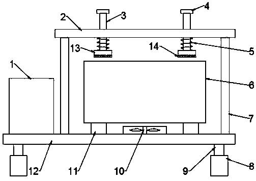
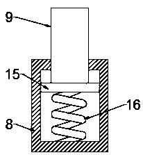
[0022] see Figure 1-2 , in an embodiment of the present invention, a lithium-ion power battery life testing device includes a battery life testing device 1 and a base plate 12, the battery life testing device 1 is installed on the base plate 12, and a support block 11 is installed on the upper end surface of the base plate 12, preferably Yes, the number of support blocks 11 is four, and the four support blocks 11 are distributed in a rectangular shape. The setting of the four support blocks 11 is convenient for placing the lithium-ion power battery body 6, and plays the role of carrying the lithium-ion power battery body 6; The lower side of the base plate 12 is provided with a shock-absorbing seat 8 and a shock-absorbing inner rod 9, the shock-absorbing inner rod 9 is connected to the lower end surface of the base plate 12, the shock-absorbing seat 8 is an internal hollow structure, and the shock-absorbing inner rod 9 runs through the shock-absorbing seat 8 and is slidably c...

Embodiment 2

[0026] see Figure 1-2 , in the embodiment of the present invention, a lithium-ion power battery life testing device is different from embodiment 1 in that a top plate 2 is provided on the upper side of the bottom plate 12, and a support column 7 is connected between the top plate 2 and the bottom plate 12, Preferably, the number of support columns 7 is four, and the tops of the four support columns 7 are respectively connected to the lower end surface of the top plate 2 near the four corners. The top plate 2 is provided with a battery pressing mechanism, which can Compress the lithium-ion power battery body 6 to avoid movement or shaking of the lithium-ion power battery body 6 during the test.

[0027] Specifically, the battery pressing mechanism includes a sliding bar 3 and a pressing plate 13, the sliding bar 3 runs through the top plate 2 and is slidably connected with it, so that the sliding bar 3 can slide up and down, and the pressing plate 13 is arranged at the bottom ...


PUM


Abstract

The invention relates to the technical field of lithium-ion power battery life testing, and specifically relates to a lithium-ion power battery life testing device. The device comprises battery life testing equipment and a bottom plate, wherein the upper end face of the bottom plate is equipped with support blocks, the lower side of the bottom plate is provided with shock-absorbing seats and shock-absorbing inner rods, the shock-absorbing inner rods are connected to the lower end face of the bottom plate, each shock-absorbing inner rod passes through the top wall of the corresponding shock-absorbing seat and is slidably connected with the shock-absorbing seat, the bottom end of each shock-absorbing inner rod is connected with a sliding plate, the sliding plate is located in the shock-absorbing seat, the sliding plate is slidably connected with the inner wall of the shock-absorbing seat, the lower side of the sliding plate is provided with a second spring, one end of the second spring is connected to the sliding plate, and the other end is connected to the bottom wall of the shock-absorbing seat. The lithium-ion power battery life testing device achieves an effect of buffering and absorbing the shock by using the up-and-down movement of the shock-absorbing inner rods and the sliding plates and the buffer of the second springs through the cooperation of the shock-absorbing innerrods, the shock-absorbing seats, the sliding plates and the second springs when the lithium-ion power battery life testing device is used.

Description

technical field [0001] The invention relates to the technical field of life testing of lithium ion power batteries, in particular to a life testing device for lithium ion power batteries. Background technique [0002] Lithium-ion power battery is a new type of high-energy battery successfully developed in the 20th century. The negative electrode of this battery is lithium metal, and the positive electrode is MnO 2 , SOCL 2 , (CFx)n, etc. It became practical in the 1970s. Because of its advantages of high energy, high battery voltage, wide operating temperature range, and long storage life, it has been widely used in military and civilian small electrical appliances. [0003] During the development process of lithium-ion power battery, it needs to be tested for life, and the life-testing device of lithium-ion power battery in the prior art basically does not have the function of shock absorption, and the internal components of the battery may be damaged when vibration and...

Claims


Application Information

Patent Timeline
IPC IPC(8): H01M10/42H01M10/613H01M10/6563F16F15/04
CPCF16F15/04H01M10/4285H01M10/613H01M10/6563Y02E60/10
Inventor 周翔升鞠群张宗林王磊庄家庆袁伟高浚哲
Owner 山东高质新能源检测有限公司
Why Eureka
Try Eureka