Deployable rigid reflector antenna

A reflector and antenna technology, applied in the field of aerospace satellite communications, can solve problems such as difficulty in guaranteeing profile accuracy

Active Publication Date: 2019-08-02
XIDIAN UNIV
View PDF6 Cites 2 Cited by
  • Summary
  • Abstract
  • Description
  • Claims
  • Application Information

AI Technical Summary

Problems solved by technology

[0004] The purpose of the present invention is to provide a deployable rigid reflector antenna, which solves the problem that the surface accuracy is difficult to guarantee caused by the complex on-orbit measurement and adjustment system, and realizes solid reflector antennas with large aperture, high precision, high rigidity, and high storage rate. Surface Antenna

Method used


Image

  • Deployable rigid reflector antenna
  • Deployable rigid reflector antenna
  • Deployable rigid reflector antenna

Examples


Embodiment Construction

[0029] In order to make the technical problems, technical solutions and advantages to be solved by the present invention clearer, the following will describe in detail with reference to the drawings and specific embodiments.

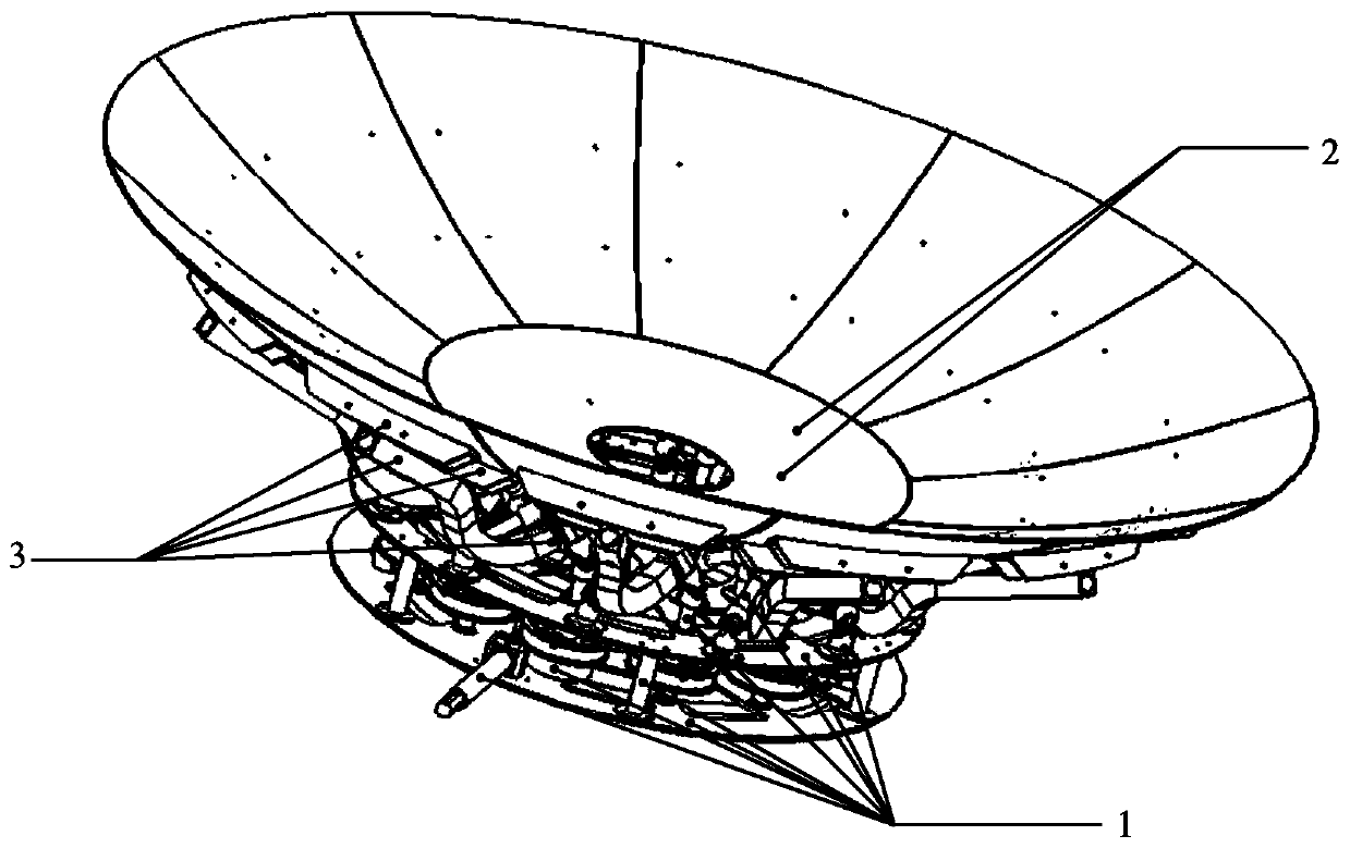
[0030] See figure 1 , figure 1 is a schematic diagram of a deployable rigid reflector antenna provided by an embodiment of the present invention, as shown in figure 1 As shown, an embodiment of the present invention provides a deployable rigid reflector antenna, which includes:

[0031] Support base assembly 1, central fixed panel assembly 2 and expandable panel assembly 3;

[0032] The support base assembly 1 and the central fixed panel assembly 2 are fixedly connected;

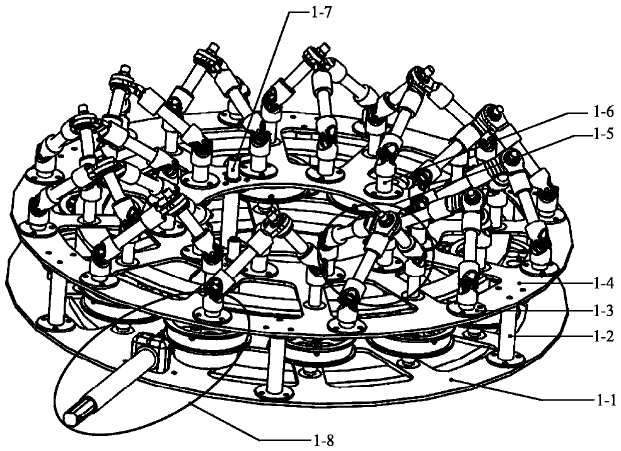
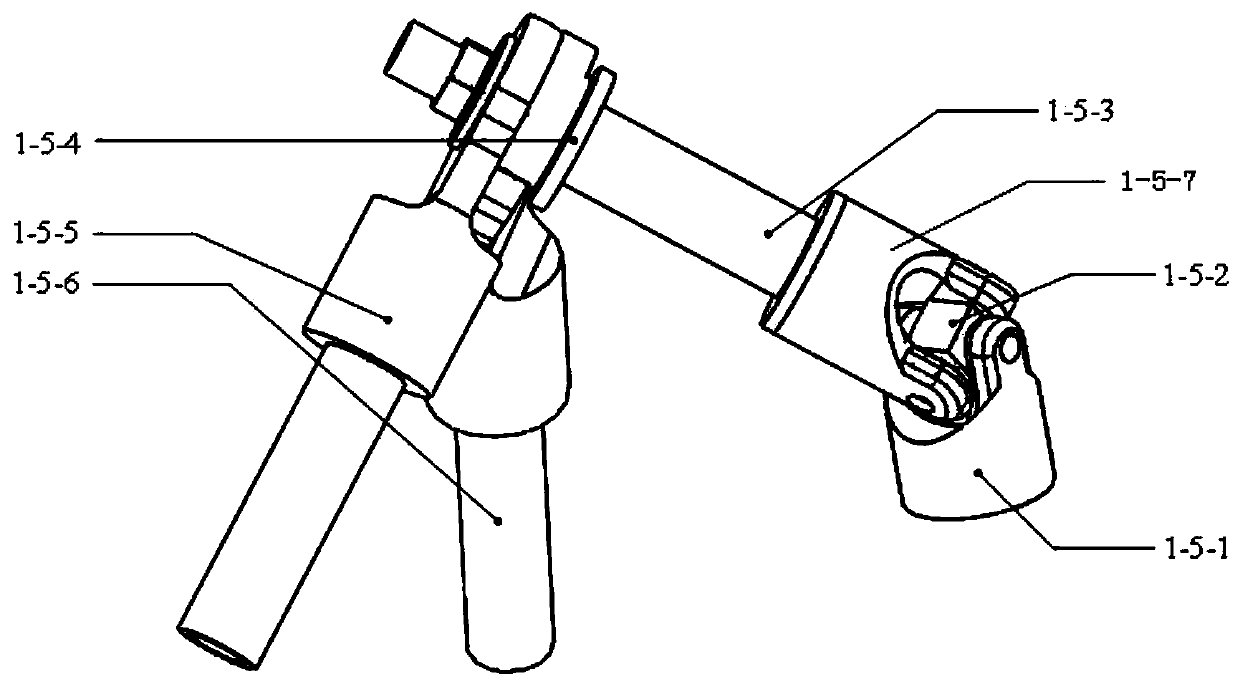
[0033] The support base assembly 1 is fixedly connected to the expandable panel assembly 3 through the rotating shaft assembly assembly 1-5 of the support base assembly 1. When the rotating shaft assembly assembly 1-5 rotates, the expandable panel assembly 3 is driven to expand, so ...


PUM


Abstract

The embodiment of the invention provides a deployable rigid reflector antenna. The antenna comprises a support base assembly 1, a central fixing panel assembly 2 and a deployable panel assembly 3. Thesupport base assembly 1 and the central fixing panel assembly 2 are fixedly connected. The support base assembly 1 is fixedly connected with the deployable panel assembly 3 through the rotating shaftassembling components 1-5 of the support base assembly 1. When the rotating shaft assembling components 1-5 rotate, the deployable panel assembly 3 is driven to deploy so that the central fixing panel assembly 2 and the deployed deployable panel assembly 3 form a complete antenna reflector together. According to the deployable rigid reflector antenna, the deployable panel assembly is driven to rotate and deploy through the rotating shaft assembling components of the support base assembly so that the solid reflector antenna with large aperture, high accuracy, high rigidity and high storage rate can be realized.

Description

technical field [0001] The invention relates to the field of aerospace satellite communication, in particular to a deployable rigid reflection surface antenna. Background technique [0002] The reflector antenna has the characteristics of high single antenna gain and wide frequency band, so it is widely used in satellite communication, microwave communication relay, mobile communication base station, etc. Areas such as deep space communications play an important role. Except for satellite communications, the reflective surfaces of commonly used antenna structures today are mostly composed of rigid materials, which are large in volume and mass and cannot be folded and compressed. These shortcomings limit the application of such antennas. In the field of satellite communications, due to the limitation of the carrying mass and capacity of the space vehicle, the large-aperture antenna must be a deployable / foldable antenna, that is, the antenna is folded and stored in the fairin...

Claims


Application Information

Patent Timeline
Patent Type & Authority Applications(China)
IPC IPC(8): H01Q1/08H01Q15/16
CPCH01Q1/288H01Q15/162
Inventor 杨东武丁延康张逸群孙梓涵
Owner XIDIAN UNIV
Why Eureka
Try Eureka