Method and system for realizing L3VPN based on two-dimensional routing protocol

A routing protocol and routing technology, applied in the field of implementing L3VPN based on two-dimensional routing protocol, can solve the problems of limited functions and services, reducing the flexibility of network routing and forwarding, etc.

Active Publication Date: 2019-08-02
TSINGHUA UNIV
View PDF8 Cites 2 Cited by
  • Summary
  • Abstract
  • Description
  • Claims
  • Application Information

AI Technical Summary

Problems solved by technology

This method reduces the flexibility of network routing and forwarding, making the functions and services provided by the network limited

Method used


Image

  • Method and system for realizing L3VPN based on two-dimensional routing protocol
  • Method and system for realizing L3VPN based on two-dimensional routing protocol
  • Method and system for realizing L3VPN based on two-dimensional routing protocol

Examples


example 1

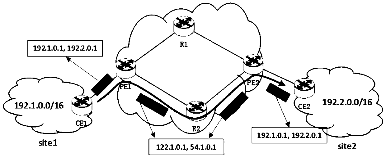
[0055] Example 1, such as image 3 As shown, site1 and site2 are respectively connected to a carrier network and belong to the same VPN service. The intranet IP segment of site1 is 192.1.0.0 / 16, and the intranet IP segment of site2 is 192.2.0.0 / 16. The routers in the carrier's network run two-dimensional routing. Assume that a packet with source address 192.1.0.1 and destination address 192.2.0.1 is sent from site1 to site2. CE1 will send the packet to PE1. PE1 finds out the pair corresponds to the public network pair, and then the message is according to Figure 4 Encapsulate in the IPIP mode shown, that is, insert an IP header carrying a public network address pair into the original. It should be pointed out that the public network address corresponding to the mapping relationship can ensure that the packet is forwarded to the destination egress route PE on the one hand, and on the other hand, it is convenient to ensure the routing policy. For example, in this example, it...

example 2

[0056] Example 2, such as Figure 5 As shown, in the embodiment of the present invention, the message sent from site1 to site2 carries the address pair , and is encapsulated at PE1 and then forwarded to the egress route PE2. To achieve network traffic load balancing, PE1 can encapsulate original packets according to a certain proportion of public network address pairs. For example, in this example, for packets carrying , PE1 50% of the packets are encapsulated as packets, these packets will reach PE2 through router R1, and the other 50% of the packets are encapsulated as packets, these The packet will reach PE2 through router R2, thus realizing the effect of load balancing.

example 3

[0057] Example three, such as Figure 6 Shown is a scenario of distinguishing intranet services. For example, in site1, a message with an address of 192.1.1.0 / 24 is common customer information, which can be forwarded to the destination site2 through a regular path (path through R1), while a message with an address of 192.1.1.0 / 24 The message with the address of 192.1.2.0 / 24 is confidential information, and it is necessary to select a highly secure path (the path through R2, such as a security detection device deployed) for separate forwarding, and then reach the destination site2. Therefore, the customer requirement in the embodiment of the present invention is that packets carrying are forwarded to developed PE2 through R1, and packets carrying are forwarded through R2 to developed PE2. PE2. Therefore, when PE1 receives the packet, it needs to match the intranet address pair of the packet, and then encapsulate it into different public network address pairs, so as to reach ...


PUM


Abstract

The invention discloses a method and system for realizing L3VPN based on a two-dimensional routing protocol, and the method comprises the following steps of starting an L3VPN network, and obtaining aroute to each user station; enabling the user in the source user site to send a message to the user in the target user site, and send the message to the entrance of the first edge routing device; using the first edge routing device to package the message according to the public network IP address of the message; and forwarding the packaged message to an outlet of the first edge routing device through the matching of the two-dimensional route for decapsulation, and forwarding the message to the target user station through an inlet of the second edge routing device. The method inherits the flexible control of the two-dimensional routing, is based on the advantages of existing protocol expansion, gradual deployment and the like, not only the functional requirements of the VPN are met, but also the policy routing in the same VPN network can be realized.

Description

technical field [0001] The invention relates to the technical field of Internet routing, in particular to a method and system for realizing L3VPN based on a two-dimensional routing protocol. Background technique [0002] The public network is a network built by operators for public users. A virtual private network (Virtual Private Network, VPN) is a remote access technology that realizes a virtual private network through a public network. A virtual private network does not need to have an actual long-distance physical data line. Although it shares a physical channel with other Internet services, it can realize a dedicated network function with a separate physical line. Specifically, users can access the internal network of the unit to which the VPN belongs (such as a company) in different geographical locations through the VPN, and users can freely access the internal network resources of the company as if they are inside the company. If you want to use VPN, you need to bu...

Claims


Application Information

Patent Timeline
Patent Type & Authority Applications(China)
IPC IPC(8): H04L12/741H04L12/46H04L45/42H04L45/74H04L45/586
CPCH04L45/74H04L12/4641H04L12/4633H04L45/745H04L45/64H04L45/34H04L45/42H04L45/566H04L45/586
Inventor 徐明伟耿男杨芫董恩焕
Owner TSINGHUA UNIV
Why Eureka
Try Eureka