SMT heavy industry nozzle

A nozzle and heavy industry technology, applied in electrical components, printed circuit manufacturing, electrical components, etc., can solve the problems of unreachable components, shorten heating time, and fix component space, improve work efficiency, speed up heat accumulation time, and avoid temperature drain effect

Active Publication Date: 2019-08-02
SUZHOU INST OF TRADE & COMMERCE
View PDF9 Cites 0 Cited by
  • Summary
  • Abstract
  • Description
  • Claims
  • Application Information

AI Technical Summary

Problems solved by technology

[0005] Although the SMTT heavy industry nozzle solves the problem of uniform heating and shortening the heating time, due to the relatively fixed space of the components, it is not possible to place larger components, and at the same time, the temperature cannot be adjusted, and the components cannot reach the optimal heating temperature.

Method used


Image

  • SMT heavy industry nozzle
  • SMT heavy industry nozzle

Examples


Embodiment 1

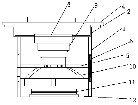
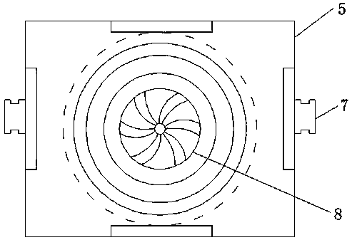
[0029] Such as figure 1 with figure 2 As shown, an SMT heavy industry nozzle includes a shell, the top of the shell is provided with a cover plate, the cover plate is connected with a connector, the connector can be connected with the air outlet of the heater, and the cover plate is provided with an air inlet , The housing is provided with a partition, two sides of the partition are respectively provided with sliders, and the two side walls of the housing and the slider are respectively provided with vertically arranged sliding grooves, Sliding up and down in the sliding groove makes the partition move up and down in the housing. A through hole is opened in the middle of the partition. The through hole is aligned with the air inlet in the cover plate. An impeller is installed in the through hole. There is a corrugated pipe connected to the air inlet, and the inner side of the corrugated pipe is lined with a layer of glass fiber cloth. The glass fiber cloth layer can play a rol...

Embodiment 2

[0031] A rework heating method for SMT heavy industry nozzles, the specific plan is as follows:

[0032] Step 1. Put the component into the component container in the SMT heavy industry nozzle, place the soldered part on the component facing the heating inlet in the component container, and adjust the partition in the shell to the closest to the component Position, turn on the heater to heat the component, record the time required for the solder attached to the component to reach the melting point, and take out the component after recording;

[0033] Step 2. Take the same type of component as in Step 1 and put it into the component container again, adjust the partition in the housing to the position farthest away from the component, turn on the heater to heat the component, and record the solder attached to the component The time required to reach the melting point, take out the component after recording;

[0034] Step 3. After repeating the process of step 1 and step 2 each 5 times...


PUM


Abstract

The invention relates to a SMT heavy industry nozzle comprising a shell. A cover plate is arranged on the top of the shell. A connector is connected on the cover plate. The connector can be butted with the air opening of a heater. An air inlet is arranged on the cover plate. A separating plate is arranged in the shell. The two sides of the separating plate are provided with a slide block respectively. The two side walls corresponding to the slide blocks of the shell are respectively provided with a vertically arranged slide groove. The separating plate is enabled to move upward and downward inthe shell by upward and downward sliding of the slide blocks in the slide grooves. A through hole is arranged in the middle of the separating plate. The through hole is aligned with the air inlet ofthe cover plate. Bellows are connected between the through hole and the air inlet. A container used for accommodating the components on the circuit board is formed between the separating plate and thebottom end of the shell. The function of adjusting the size of the space for the components can be realized by arranging the cover plate to move upward and downward in the shell so that different sizes of components can be accommodated and the effect of temperature control can be achieved by adjusting the distance between the cover plate and the components.

Description

Technical field [0001] The invention belongs to the SMT technical field, and specifically relates to an SMT heavy industry nozzle. Background technique [0002] SMT stands for Surface Mount Technology (Surface Mount Technology) (abbreviation of Surface Mount Technology), which is currently the most popular technology and process in the electronics assembly industry. SMT has the characteristics of high assembly density, small size and light weight of electronic products. The volume and weight of SMT components are only about 1 / 10 of that of traditional plug-in components. Generally, after SMT is adopted, the volume of electronic products is reduced by 40% to 60%. Reduced by 60% to 80%, high reliability, strong earthquake resistance, low solder joint defect rate, good high frequency characteristics, reduced electromagnetic and radio frequency interference, easy to achieve automation, and improve production efficiency. Reduce costs by 30% to 50%. Save materials, energy, equipment,...

Claims


Application Information

Patent Timeline
IPC IPC(8): H05K3/34H05K13/04
CPCH05K3/3494H05K13/0486
Inventor 石冬喜
Owner SUZHOU INST OF TRADE & COMMERCE
Why Eureka
Try Eureka