Drying grain tank of combine harvester

A technology for combine harvesters and grain boxes, which is applied to harvesters, cutters, agricultural machinery and implements, etc. It can solve problems such as affecting drying efficiency, difficult to discharge grain boxes, and grain coking, so as to improve work efficiency, save electric energy, The effect of simple structure

Active Publication Date: 2019-08-06
JIANGSU UNIV
View PDF9 Cites 5 Cited by
  • Summary
  • Abstract
  • Description
  • Claims
  • Application Information

AI Technical Summary

Problems solved by technology

The above invention patents can realize the drying treatment of materials, but it is difficult to apply to the drying of grains when the combine harvester is harvested in the field
Due to the large volume of the grain box of the combine harvester, the grain is continuously transported into the grain box and accumulated in the grain box with a thickness of 40-50 cm. It is difficult for the existing drying technology to directly apply to the real-time drying of the grain in the grain box of the existing combine harvester when harvesting in the field.
If the temperature in the grain tank cannot be automatically controlled during the drying process, the temperature will be too high and the grain will be scorched, which will seriously affect the quality of the grain
At the same time, it is difficult to ensure uniform drying of all the grains when drying several tons of grains, and it is also difficult for the humid gas evaporated from the grains to be quickly discharged from the grain tank, which affects the drying efficiency

Method used


Image

  • Drying grain tank of combine harvester
  • Drying grain tank of combine harvester
  • Drying grain tank of combine harvester

Examples


Embodiment Construction

[0031] The present invention will be further described below in conjunction with the accompanying drawings and specific embodiments, but the protection scope of the present invention is not limited thereto.

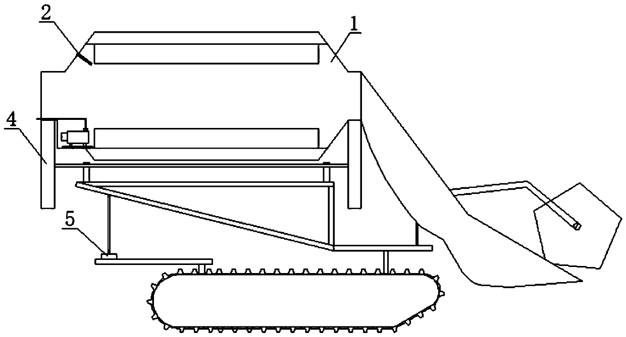
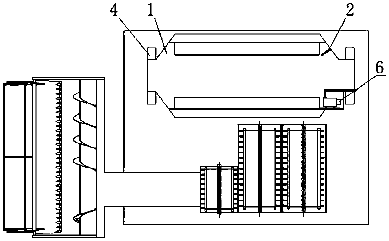
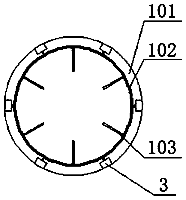
[0032] like figure 1 and figure 2 As shown, the dry grain box of the combine harvester of the present invention comprises a grain box 1, a temperature relay 2, a microwave heater 3, a transmission device 4, a frame 5 and a vacuum system; the temperature relay 2 is fixed on the grain box 1 at the tail end of the inner wall, the temperature relay 2 is used to detect the temperature in the grain tank 1; the microwave heater 3 is uniformly fixed on the inner wall of the grain tank 1; the transmission device 4 is located below the grain tank 1 for The grain tank 1 rotates on its own; the inclined frame 5 is located below the transmission device 4; the vacuum pump 6 is located at the tail end of the inner wall of the rotating grain tank 1, and can be arranged symmetrically wi...


PUM


Abstract

The invention provides a drying grain tank of a combine harvester. The drying grain tank comprises a rack and a grain tank body, and a drying system is installed in the grain tank body and used for drying grains in the grain tank body; the grain tank body is rotatably installed on the rack. A shell of the grain tank body is provided with an outer gear, and the grain tank body rotates by itself through a transmission device. The transmission device comprises transmission gears and a transmission shaft; the transmission shaft is provided with the transmission gears; the transmission gears are meshed with the outer gear on the shell of the grain tank body. Cereal stirring plates evenly distributed in the circumference direction are arranged in the shell of the grain tank body. According to the drying grain tank, cereals in the grain tank body are dried through a heating device, vapor volatilized from the cereals is pumped out of the grain tank body through a vacuum pump, and the drying environment in the grain tank body is maintained. In the drying process, the cereals in the grain tank body are continuously stirred through the cereal stirring plates, and the situation is avoided thatsince the cereals are unevenly heated, the drying effect is influenced.

Description

technical field [0001] The invention relates to the field of combine harvesting and storage devices, in particular to a dry grain box of a combine harvester. Background technique [0002] The grain tank is an important component of the combine harvester. It is used to store the grain obtained by the threshing and cleaning device. The newly harvested grain contains a lot of water, and it needs to be dried intensively before being stored in the grain depot, otherwise it will easily lead to deterioration of the grain . The entire drying process is not only time-consuming, but also cumbersome and requires a lot of manpower and material resources. Therefore, rapid drying of the grains in the grain bins during the harvesting process can significantly improve work efficiency. During the grain unloading process, the structure of the rotating parts such as the auger is complicated, and there are often failures such as transmission blockage during the grain transportation process. Th...

Claims


Application Information

Patent Timeline
Patent Type & Authority Applications(China)
IPC IPC(8): A01D41/133A01D41/12
CPCA01D41/1208A01D41/133
Inventor 唐忠张浩天周跃鹏李宇李禧尧
Owner JIANGSU UNIV
Why Eureka
Try Eureka