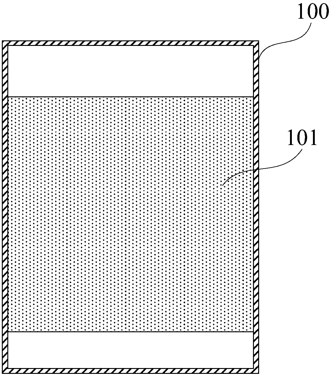
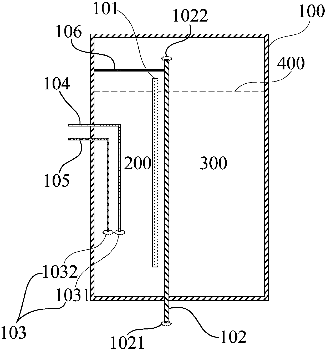
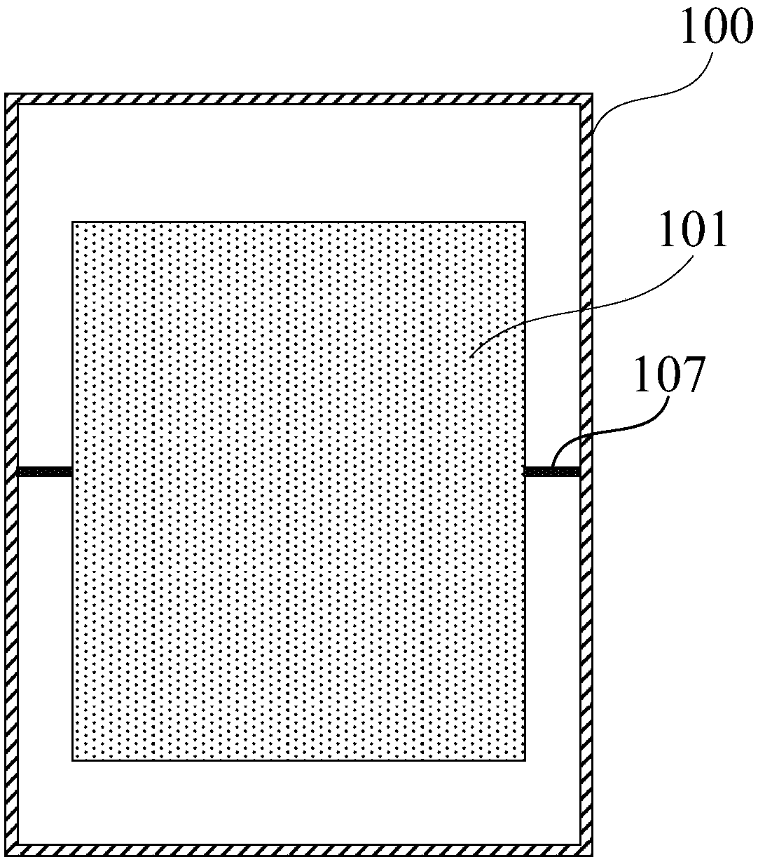
Liquid box and liquid circulation device

A liquid circulation and liquid tank technology, applied in the direction of foam dispersion/prevention, can solve problems such as troublesome operation, leakage, inconvenient manual exhaust, etc., and achieve the effect of reducing the risk of leakage and preventing damage to air bubbles

Inactive Publication Date: 2019-08-06
SHANGHAI MICRO ELECTRONICS EQUIP (GRP) CO LTD
View PDF6 Cites 1 Cited by
  • Summary
  • Abstract
  • Description
  • Claims
  • Application Information

AI Technical Summary

Problems solved by technology

However, since the circulation pipeline is continuously circulating the liquid, the generation of air bubbles is also continuous, and regular manual exhaust cannot completely prevent the air bubbles from being sucked into the circulation pipeline by the pump body
In addition, due to the limited building space, the area reserved for maintenance is very limited. It is extremely inconvenient to manually exhaust gas when there is a problem of gas entering the circulation pipeline, and it is necessary to open the pump tank to vent the air, which is troublesome to operate and has the risk of leakage

Method used


Image

  • Liquid box and liquid circulation device
  • Liquid box and liquid circulation device
  • Liquid box and liquid circulation device

Examples


Embodiment Construction

[0029] The technical solutions of the present invention will be further described below in conjunction with the accompanying drawings and through specific implementation methods. It should be understood that the specific embodiments described here are only used to explain the present invention, but not to limit the present invention. In addition, it should be noted that, for the convenience of description, only some structures related to the present invention are shown in the drawings but not all structures.

[0030] In describing the present invention, it is to be understood that the terms "upper", "lower", "front", "rear", "vertical", "horizontal", "top", "bottom", "inner" and " The orientation or positional relationship indicated by "outside", etc. is based on the orientation or positional relationship shown in the drawings, and is only for the convenience of describing the present invention and simplifying the description, rather than indicating or implying that the referr...


PUM


Abstract

The invention discloses a liquid box and a liquid circulation device. The liquid box comprises a box body, a partition plate arranged in the box body, and an exhaust tube for communicating the internal of the box body with an external environment; the partition plate divides the box body into a liquid inlet chamber and a liquid outlet chamber, the bottom of the liquid inlet chamber is communicatedwith the bottom of the liquid outlet chamber, and the top of the liquid inlet chamber is communicated with the top of the liquid outlet chamber; and the partition plate is used for blocking bubbles generated in the liquid inlet chamber from flowing to the liquid outlet chamber, and the exhaust tube is used for discharging the overflowing bubbles. The problems of incomplete avoiding of the bubblesfrom being sucked into a circulation pipeline by a pump body, troublesome operation and liquid leakage risk of manual exhaust are solved, and the liquid box has the advantages of realization of automatic exhausting, prevention of the generated bubbles from entering the liquid circulation pipeline, reduction of the risk of liquid leakage, simple structure and low cost.

Description

technical field [0001] Embodiments of the present invention relate to the technical field of liquid circulation systems, and in particular, to a liquid tank and a liquid circulation device. Background technique [0002] Liquid circulation systems or equipment are widely used in various industries, such as fan coil systems in the HVAC industry, lithography machine environmental subsystems in the semiconductor industry, and external auxiliary liquid temperature control equipment for etching machines. [0003] In equipment with high requirements on the operating environment of the equipment, the liquid circulation system is an important guarantee to ensure the normal operation of the equipment. In semiconductor equipment, especially high-precision lithography machines, the liquid circulation system needs to continuously and reliably provide the operating environment for the normal operation of the lithography machine. [0004] However, the generation of air bubbles in the liqu...

Claims


Application Information

Patent Timeline
Patent Type & Authority Applications(China)
IPC IPC(8): B01D19/02
CPCB01D19/02
Inventor 刘伟高玉英
Owner SHANGHAI MICRO ELECTRONICS EQUIP (GRP) CO LTD
Why Eureka
Try Eureka