Synchronous transferring device

A transfer device and component technology, applied in the directions of transportation and packaging, conveyor objects, etc., can solve the problems of complex structure, rollover or lodging, and difficulty in ensuring levelness, so as to achieve a stable guiding process, improve stability, and ensure the level of degree of effect

Pending Publication Date: 2019-08-06
SUZHOU RS TECH
View PDF0 Cites 4 Cited by
  • Summary
  • Abstract
  • Description
  • Claims
  • Application Information

AI Technical Summary

Problems solved by technology

[0002] In the field of non-standard automation equipment, it is often necessary to use a synchronous transfer device for synchronously transporting materials. There are several problems in the existing synchronous transfer device: First, the structure is complex, resulting in complicated disassembly steps and occupying an area after assembly. The area is large; secondly, the design of the guide structure is unreasonable, resulting in unsmooth handling, and a large range of vibration during the handling process. For handling small materials, large vibrations are likely to cause unstable material handling, and for high assembly precision requirements As far as the station is concerned, it cannot meet the requirements of high-precision operations; thirdly, during the handling process of materials, its levelness is difficult to ensure, and it is very easy to roll over or fall, which will affect the assembly accuracy and even lead to final assembly failure; finally, the nozzle’s It is difficult to ensure the stability of the starting and ending positions, which may easily cause the position deviation of the suction nozzle when picking up and placing the material, which will eventually lead to the failure of material transfer

Method used


Image

  • Synchronous transferring device
  • Synchronous transferring device
  • Synchronous transferring device

Examples


Embodiment Construction

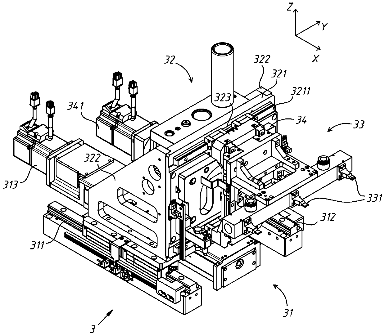
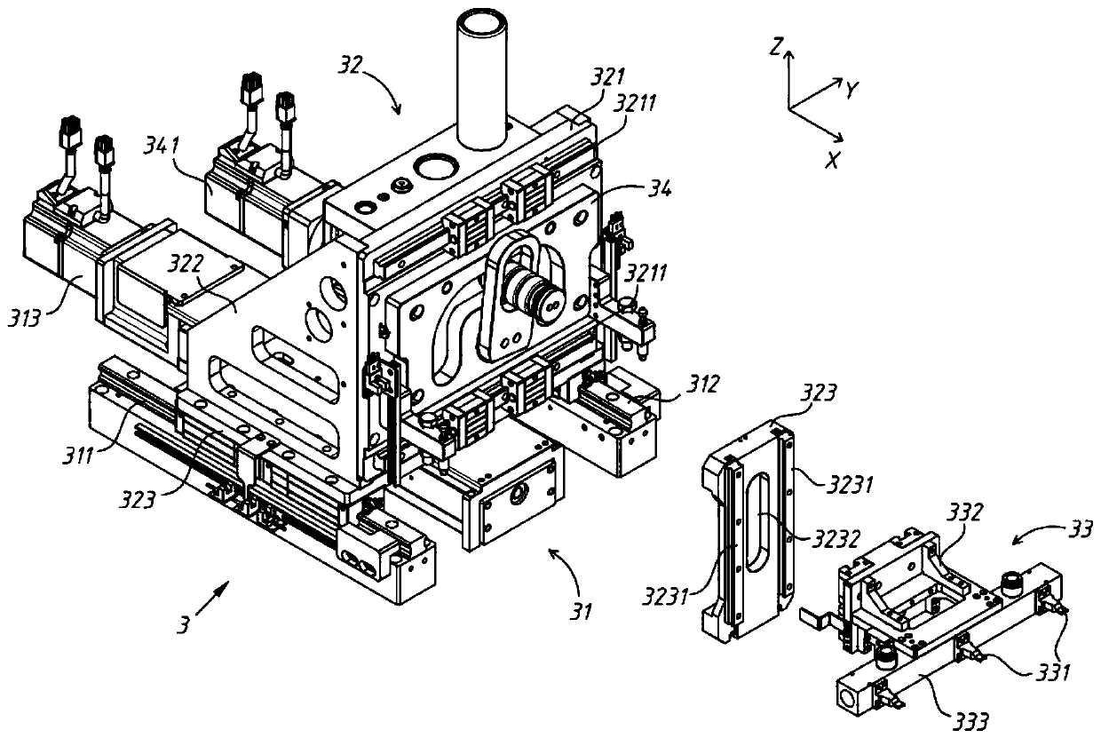
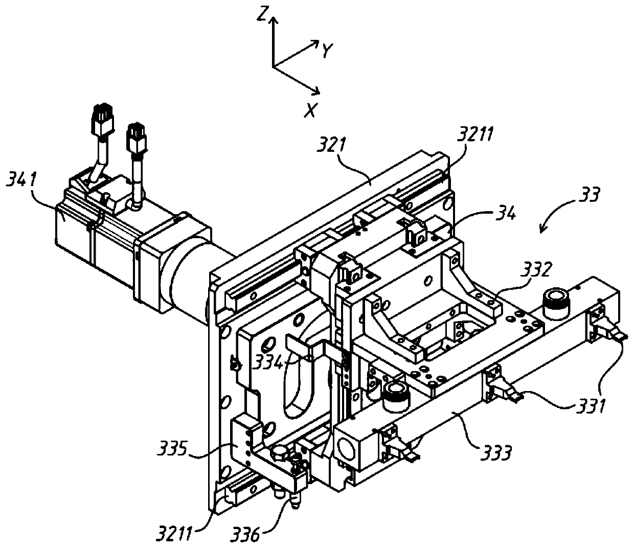
[0053] The present invention will be further described in detail below in conjunction with the accompanying drawings, and the aforementioned and other objects, features, aspects and advantages of the present invention will become more apparent, so that those skilled in the art can implement them with reference to the description. In the drawings, the shapes and dimensions may be exaggerated for clarity, and the same reference numerals will be used throughout to designate the same or like parts. In the following description, terms such as center, thickness, height, length, front, back, rear, left, right, top, bottom, upper, lower, etc. are based on the orientation or positional relationship shown in the drawings. In particular, "height" corresponds to the dimension from top to bottom, "width" corresponds to the dimension from left to right, and "depth" corresponds to the dimension from front to back. These relative terms are for convenience of description and are generally not ...


PUM


Abstract

The invention discloses a synchronous transferring device. A horizontal movement assembly, a transferring support, a guiding assembly and a synchronous sucking assembly are included, wherein the transferring support is in sliding connection with the horizontal movement assembly; the guiding assembly comprises a guiding plate fixedly connected with the transferring support, a traction head embeddedin the guiding plate, and a transmission driving assembly in transmission connection with the traction head; the synchronous sucking assembly is in transmission connection with one end of the traction head; and the traction head can be driven by a transmission driving part to do the reciprocating swinging movement in the vertical plane. The synchronous transferring device is compact in structureand small in volume, the guiding process is stable, a plurality of materials can be carried synchronously, the levelbess of the materials can also be guaranteed in the material carrying process, and therefore the requirement for carrying tiny materials and performing high-precision assembling is met; and besides, the starting and terminating positions of a sucking nozzle can also be stably limited, and the stability of material sucking and placing steps is improved.

Description

technical field [0001] The invention relates to the field of non-standard automation, in particular to a synchronous transfer device. Background technique [0002] In the field of non-standard automation equipment, it is often necessary to use a synchronous transfer device for synchronously transporting materials. There are several problems in the existing synchronous transfer device: First, the structure is complex, resulting in complicated disassembly steps and occupying an area after assembly. The area is large; secondly, the design of the guide structure is unreasonable, resulting in unsmooth handling, and a large range of vibration during the handling process. For handling small materials, large vibrations are likely to cause unstable material handling, and for high assembly precision requirements As far as the station is concerned, it cannot meet the requirements of high-precision operations; thirdly, during the handling process of materials, its levelness is difficult...

Claims


Application Information

Patent Timeline
Patent Type & Authority Applications(China)
IPC IPC(8): B65G47/90
CPCB65G47/901
Inventor 王瑞吴加富缪磊吴天水马伟刘宣宣刘龙海
Owner SUZHOU RS TECH
Why Eureka
Try Eureka