Supercharge Your Innovation With Domain-Expert AI Agents!

High-efficient centrifugal impeller

A hub, equidistant technology, used in non-variable-capacity pumps, vane support elements, liquid fuel engines, etc., to solve problems such as dynamic imbalance

Active Publication Date: 2019-08-06
CARRIER CORP
View PDF5 Cites 3 Cited by
  • Summary
  • Abstract
  • Description
  • Claims
  • Application Information

AI Technical Summary

Problems solved by technology

For example, when the center axis of mass of the impeller deviates from the center of rotation of the rotor shaft, centrifugal force is generated, resulting in dynamic imbalance

Method used


Image

  • High-efficient centrifugal impeller
  • High-efficient centrifugal impeller
  • High-efficient centrifugal impeller

Examples


Embodiment Construction

[0030] A detailed description of one or more embodiments of the disclosed apparatus and methods is presented herein by way of illustration and not limitation, with reference to the accompanying drawings.

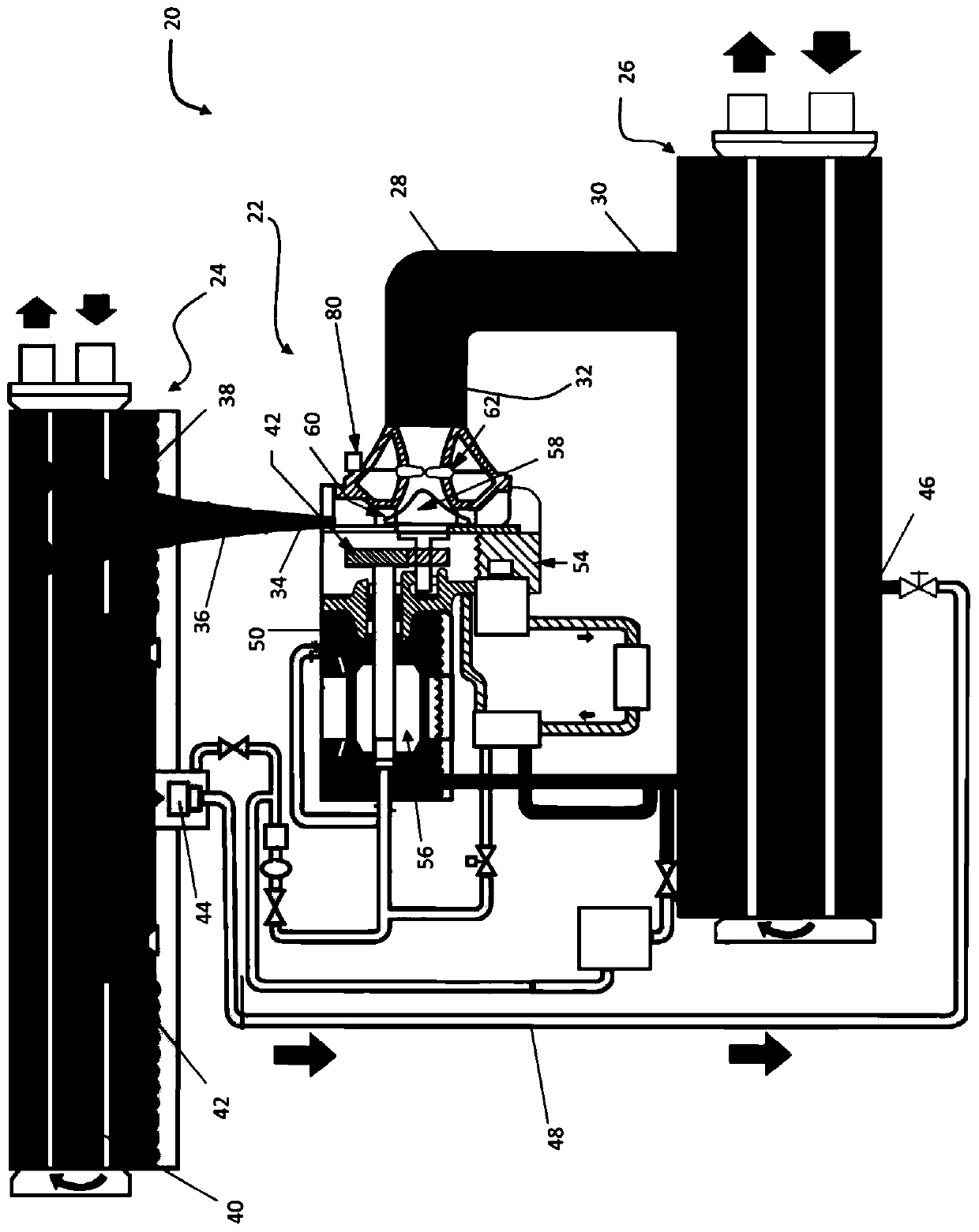
[0031] now refer to figure 1 , illustrates an example of a refrigeration system 20 . Refrigeration system 20 includes compressor assembly 22 , condenser 24 , and evaporator 26 fluidly coupled to form a circuit. A first conduit 28 extends from adjacent an outlet 30 of the evaporator 26 to an inlet 32 ​​of the compressor assembly 22 . An outlet 34 of compressor assembly 30 is coupled to an inlet 38 of condenser 24 by a conduit 36 ​​. In one embodiment, condenser 24 includes a first chamber 40 , and a second chamber 42 accessible only from the interior of first chamber 40 . A float valve 44 in the second chamber 42 is connected to an inlet 46 of the evaporator 26 by another conduit 48 .

[0032] Depending on the size of refrigeration system 20, compressor assembly 22 may in...


PUM


Abstract

The invention relates to a high-efficient centrifugal impeller. In particular, the invention relates to a balancing weight mountable within a balance hole of a rotary component, which includes a cylindrical body having a desired weight. An opening is formed in a portion of the body to define a hollow passageway and a mechanism couples the cylindrical body within an interior of the balance hole.

Description

Background technique [0001] Exemplary embodiments disclosed herein relate to rotating machines, such as compressors, for example, and more particularly, to systems for balancing rotating components of rotating machines. [0002] Rotating machines are commonly used in refrigeration and turbine applications. Examples of rotary machines include centrifugal compressors having an impeller fixed to a rotating shaft. Rotation of the impeller increases the pressure and / or velocity of fluid or gas moving across the impeller. During the rotation of the impeller, mass imbalances can occur, for example, due to positional deviations of the impeller relative to the rotor shaft, manufacturing tolerances during machining or the like. For example, when the center axis of the mass of the impeller deviates from the rotation center of the rotor shaft, centrifugal force is generated, resulting in dynamic imbalance. [0003] In order to prevent or minimize this unbalance and any resulting vibrat...

Claims


Application Information

Patent Timeline
Patent Type & Authority Applications(China)
IPC IPC(8): F04D29/28F04D29/66F16F15/28
CPCF04D29/284F04D29/662F04D29/666F16F15/28F04D29/051F05D2250/281F01D5/027F04D29/66F01D5/10F05D2220/36F05D2230/60F05D2260/15F05D2260/96F16F15/322F16F15/34
Inventor V.M.西什特拉J.陈
Owner CARRIER CORP
Features
  • R&D
  • Intellectual Property
  • Life Sciences
  • Materials
  • Tech Scout
  • Unparalleled Data Quality
  • Higher Quality Content
  • 60% Fewer Hallucinations
Learn More