Star sensor stray light test system based on real starry sky

A technology of star sensor and test system, applied in the field of astronomical navigation, can solve problems such as inaccurate test results, and achieve the effect of saving measurement time, accurate results and centralized storage

Active Publication Date: 2019-08-06
SHANGHAI AEROSPACE CONTROL TECH INST
View PDF7 Cites 5 Cited by
  • Summary
  • Abstract
  • Description
  • Claims
  • Application Information

AI Technical Summary

Problems solved by technology

Darkroom testing of stray light has the advantages of not being limited by time and place, and the equipment is fixed, but the test conclusion is only based on the calculation of the mathematical model to indirectly simulate the "output attitude" of the star sensor, rather than directly verify the "output attitude" of the product under the condition of stray light interference , may cause inaccurate test results

Method used


Image

  • Star sensor stray light test system based on real starry sky
  • Star sensor stray light test system based on real starry sky
  • Star sensor stray light test system based on real starry sky

Examples


Embodiment Construction

[0024] The present invention will be further elaborated below by describing a preferred specific embodiment in detail in conjunction with the accompanying drawings.

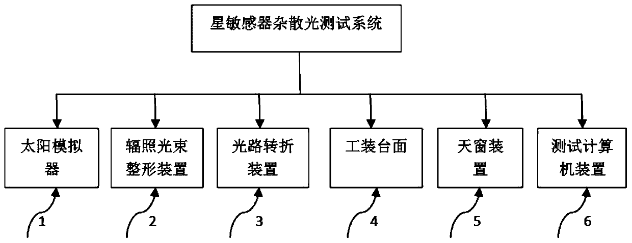
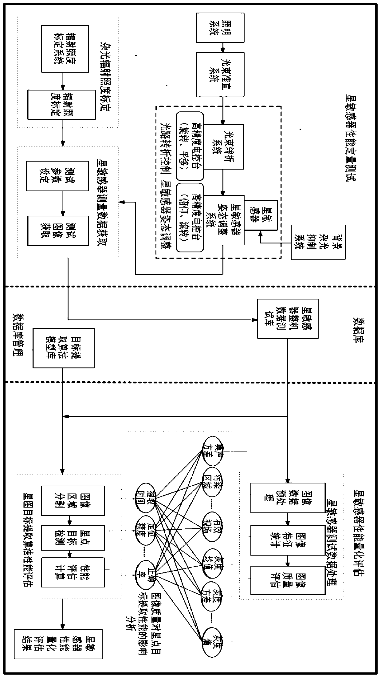
[0025] The test principle of the system is: the outgoing light of the solar simulator is shaped into parallel light by the irradiation beam shaping device and then incident on the first set of plane mirrors, and the beam is refracted by the first set of plane mirrors and then incident on the second set of planes On the reflector, after being deflected by the second set of plane reflectors, the light beam is incident on the entrance of the star sensor at different zenith angles. Turn on the star sensor to collect measurement data. During the test of the whole machine, under the control of the optical path turning device software, the first group of plane mirrors is driven to rotate, and the second group of plane mirrors is rotated and translated to adjust the direction of the background light; in the star sensor ...


PUM


Abstract

The invention relates to a star sensor stray light test system based on the real starry sky. The system comprises a solar simulator, an irradiation beam shaping device, an optical path turning device,a tooling table board, a skylight device and a test computer device. Therefore, stray light is injected into a star sensor shading hood at a given angle under the starry sky background condition andthus a test task of the stray light test is performed. The technical means is provided for the factory test of the star sensor product; and the quantitative test and quantified evaluation of the starsensor performance are completed.

Description

technical field [0001] The invention relates to the field of celestial navigation, in particular to a star sensor stray light test system based on real starry sky. Background technique [0002] The star sensor works in a harsh environment with stray light (such as sunlight, moonlight, and atmospheric light) outside the field of view of the system. It is mainly used for imaging weak and small moving objects in space, and the background stray light has a serious impact. The impact of stray light on the system, if it is mild, will reduce the signal-to-noise ratio and contrast of the target, thus affecting the detection or identification capabilities of the entire system; if it is severe, the detected target signal will be completely lost in the background of stray light, and the system cannot extract or due to uneven distribution of stray light on the image plane, a false signal is formed on the system detector, causing the system to detect a false target or even cause the enti...

Claims


Application Information

Patent Timeline
Patent Type & Authority Applications(China)
IPC IPC(8): G01C25/00
CPCG01C25/00
Inventor 任平川吴永康毛晓楠余路伟范勇黄嘉智
Owner SHANGHAI AEROSPACE CONTROL TECH INST
Why Eureka
Try Eureka