Stator cooling structure and rotary electric machine

A cooling structure and stator technology, applied in synchronous motors with stationary armatures and rotating magnets, cooling/ventilation devices, magnetic circuit shapes/styles/structures, etc., can solve the complex internal structure of the rotor and the inability to cool uniformly Stator and other problems to achieve the effect of simple structure

Inactive Publication Date: 2019-08-06
HONDA MOTOR CO LTD
View PDF5 Cites 1 Cited by
  • Summary
  • Abstract
  • Description
  • Claims
  • Application Information

AI Technical Summary

Problems solved by technology

[0005] However, in order for the refrigerant to flow from the refrigerant supply channel inside the rotor shaft to the refrigerant flow path in the inner peripheral part of the rotor core, a structure for dividing the refrigerant flow is required, which may complicate the internal structure of the rotor.
[0006] On the other hand, in the structure in which the refrigerant is dripped from the outside in the radial direction of the stator, temperature distribution may occur in the circumferential direction of the stator, and the stator may not be cooled uniformly.
[0007] Therefore, there is room for improvement in cooling the stator uniformly with a simple structure

Method used


Image

  • Stator cooling structure and rotary electric machine
  • Stator cooling structure and rotary electric machine
  • Stator cooling structure and rotary electric machine

Examples


Embodiment Construction

[0039] Hereinafter, embodiments of the present invention will be described with reference to the drawings. In the embodiment, a rotating electrical machine (motor for traveling) mounted in a vehicle such as a hybrid vehicle or an electric vehicle will be described as an example.

[0040]

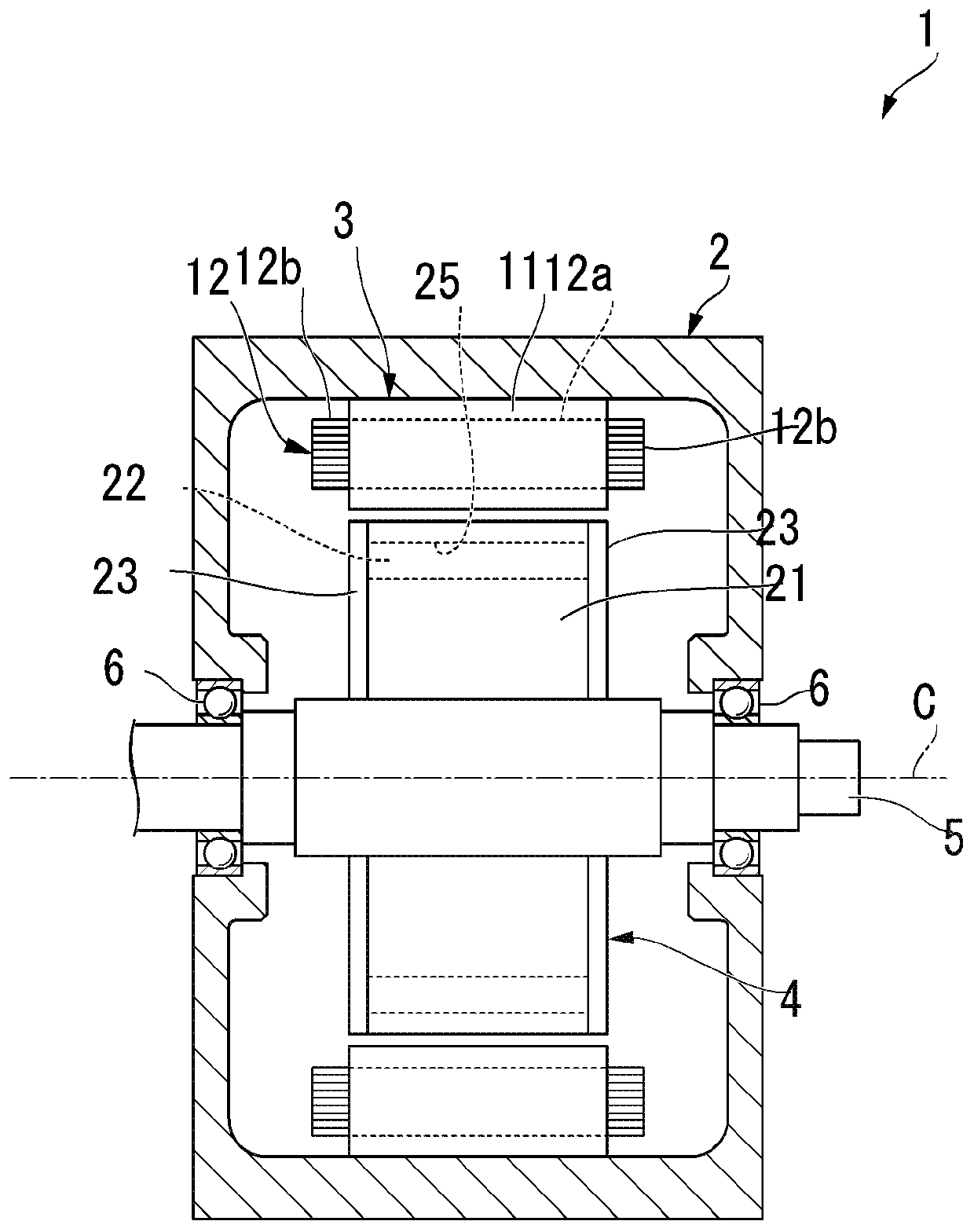
[0041] figure 1 It is a schematic configuration diagram showing the overall configuration of the rotating electric machine 1 according to the embodiment. figure 1 It is a figure including the cross section cut by the imaginary plane containing the axis C.

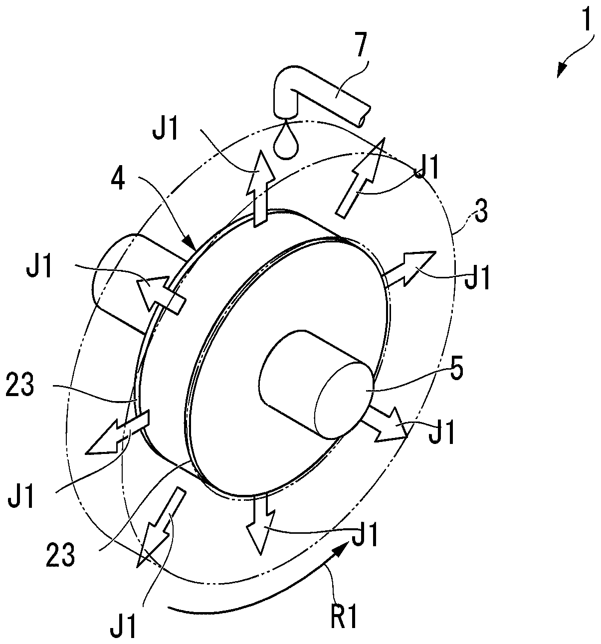
[0042] Such as figure 1 As shown, a rotating electric machine 1 includes a housing 2, a stator 3, a rotor 4, an output shaft 5, and a refrigerant supply mechanism 7 (refer to figure 2 ).

[0043] The case 2 is formed in a cylindrical box shape for housing the stator 3 and the rotor 4 . A refrigerant (not shown) is accommodated in the casing 2 . A part of the stator 3 is arranged in the housing 2 in a state of being immersed in th...


PUM


Abstract

The invention provides a stator cooling structure and a rotating electric machine, which can uniformly cool a stator by using a simple structure. The stator cooling structure of an embodiment includesa rotor (4) that is arranged on an inner side in a radial direction with respect to a stator having a tube shape; and an end surface plate (23) that is provided on an end part in an axial direction of the rotor (4), wherein a diffusion slope surface that is sloped such that a refrigerant which is externally supplied is diffused outward in the radial direction using a rotation of the rotor (4) isprovided on an outer circumferential part of the end surface plate (23).

Description

technical field [0001] The invention relates to a stator cooling structure and a rotating electrical machine. Background technique [0002] In a rotating electrical machine mounted on a hybrid vehicle, an electric vehicle, or the like, a magnetic field is formed in a stator core by supplying current to a coil, and a magnetic attraction force or a magnetic repulsion force is generated between a permanent magnet of the rotor and the stator core. Thus, the rotor rotates relative to the stator. [0003] In the above-mentioned rotating electric machine, when heat is generated during driving, the heat may cause performance degradation. Then, various studies have been conducted on a structure for cooling the rotating electric machine. For example, Japanese Patent Application Laid-Open No. 2013-55775 discloses a configuration including: a rotor shaft having a refrigerant supply port capable of supplying refrigerant from a refrigerant supply passage inside the shaft to the outside ...

Claims


Application Information

Patent Timeline
Patent Type & Authority Applications(China)
IPC IPC(8): H02K9/19
CPCH02K9/19H02K9/20H02K21/16H02K1/20
Inventor 加藤慎二
Owner HONDA MOTOR CO LTD
Why Eureka
Try Eureka