Splicing processor capable of being quickly switched

A splicing processor and fast switching technology, which is applied to color TV parts, TV system parts, TVs, etc., can solve the problems of large space occupied by heat dissipation devices, affecting interface stability, and increasing processor volume. To achieve the effect of improving heat dissipation, convenient wiring, and convenient grip

Inactive Publication Date: 2019-08-06
广州北辰信息科技有限公司
View PDF6 Cites 3 Cited by
  • Summary
  • Abstract
  • Description
  • Claims
  • Application Information

AI Technical Summary

Problems solved by technology

[0004] However, in actual use, there are still many disadvantages. For example, there are many connection sockets on the surface of the processor, which are easy to enter dust and affect the stability of the interface, and the heat dissipation device inside the processor takes up a large space, increasing the processing capacity. The volume of the device

Method used


Image

  • Splicing processor capable of being quickly switched
  • Splicing processor capable of being quickly switched
  • Splicing processor capable of being quickly switched

Examples


Embodiment 1

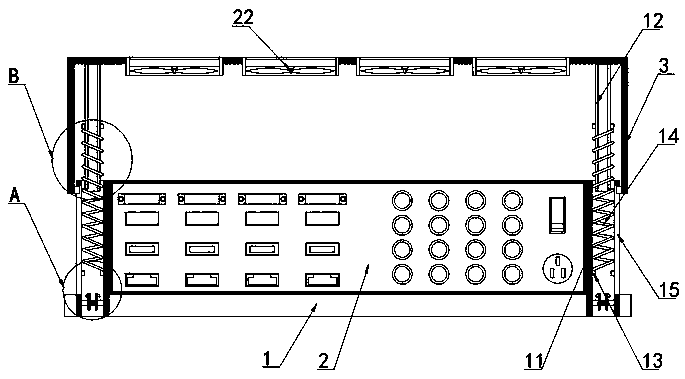
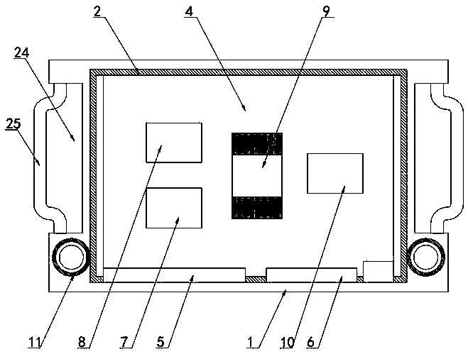
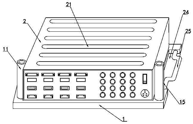
[0028] The present invention provides such Figure 1-6 The splicing processor that can be switched quickly includes a bottom plate 1, a processor body 2 is arranged on the top of the bottom plate 1, a protective shell 3 is arranged on the top of the processor body 2, and a There is a processor circuit board 4, one side of the processor circuit board 4 is provided with a data input board 5, and the other side of the processor circuit board 4 is provided with a data output board 6, and the surface of the processor circuit board 4 is A video matrix switcher 7 is provided, and a video matrix switcher 8 is arranged on one side of the video matrix switcher 7, and a multi-channel output chip 9 is arranged on one side of the video matrix switcher 8, and a multi-channel output chip 9 is arranged on one side of the video matrix switcher 8. The side is provided with a multi-channel distributor 10, both sides of the processor main body 2 are provided with fixed cylinders 11, and both side...

Embodiment 2

[0031] Further, the surface of the fixed cylinder 11 is provided with a chute 15, the inner bottom of the protective shell 3 is provided with a slider 16, the bottom of the fixed cylinder 11 is provided with a fixed block 17, and the middle part of the fixed block 17 is symmetrically provided with two A movable buckle 18, a second spring 19 is arranged between the two movable buckles 18, a buckle groove 20 is provided at the bottom of the movable column 12, when the movable column 12 is inserted into the fixed cylinder 11, the movable buckle is used 18 is buckled with the buckle groove 20 at the bottom of the movable column 12, and then the movable column 12 is fixed to realize the covering protection of the processor body 2 by the protective shell 3, and the slider 16 moves in the chute 15 to realize the protection of the protective shell 3. 3. Limiting the movement to prevent the protective shell 3 from detaching from the processor main body 2.

[0032] Further, the top surf...


PUM


Abstract

The invention discloses a splicing processor capable of being quickly switched, and particularly relates to the technical field of splicing processors. The splicing processor comprises a bottom plate,a processor main body is arranged at the top of the bottom plate, and a protective shell is arranged at the top of the processor main body; a processor circuit board is arranged in the processor mainbody, a data input board card is arranged on one side of the processor circuit board, a data output board card is arranged on the other side of the processor circuit board, a video matrix exchanger is arranged on the surface of the processor circuit board, and a video matrix switcher is arranged on one side of the video matrix exchanger. The whole processor body is wrapped with the protection shell, isolation protection is conducted on the processor, the movable column and the fixed barrel are matched, the first spring is used for pushing the movable column to drive the protection shell to move, the movable column is fixed through the movable buckle, and protection and use switching between the protection shell and the processor body are facilitated.

Description

technical field [0001] The present invention relates to the technical field of splicing processors, and more specifically, the present invention relates to a fast-switchable splicing processor. Background technique [0002] The splicing processor is one of the most important components of the LCD splicing display system. It is currently divided into two types: built-in and external. The splicing processor has high-end image processing functions such as high-definition video signal acquisition and real-time high-resolution digital image processing. Has powerful processing capabilities. [0003] The utility model patent of the patent application publication number CN201621242687.0 discloses a VR image splicing processor with pluggable multi-input interfaces, including a processor shell and a video output socket, and a small display is arranged on the front surface of the processor shell , and one side of the processor shell is provided with a processor side plate, the inside ...

Claims


Application Information

Patent Timeline
Patent Type & Authority Applications(China)
IPC IPC(8): H04N5/262H04N5/265H04N5/268H04N5/765H05K7/20
CPCH04N5/262H04N5/265H04N5/268H04N5/765H05K7/20172
Inventor 刘义
Owner 广州北辰信息科技有限公司
Why Eureka
Try Eureka