
Push type deceleration buffer adjusting structure

A buffer adjustment and push-type technology, applied in the direction of gear vibration/noise attenuation, transmission, transmission parts, etc., can solve problems such as inconvenience, inconvenient internal contact restrictions, unfavorable buffer adjustment, etc.

Active Publication Date: 2021-08-31
欧亿光信息技术(太仓)有限公司
View PDF7 Cites 0 Cited by
  • Summary
  • Abstract
  • Description
  • Claims
  • Application Information

AI Technical Summary

Problems solved by technology

[0004] There is a phenomenon that it is not convenient for internal contact restriction, it is not conducive to real-time adjustment and control, and it will cause certain inconvenience. At the same time, it is not conducive to buffer adjustment, it is not conducive to stability control, and needs to be improved

Method used


Image

  • Push type deceleration buffer adjusting structure
  • Push type deceleration buffer adjusting structure
  • Push type deceleration buffer adjusting structure

Examples


Embodiment Construction

[0034] The following will clearly and completely describe the technical solutions in the embodiments of the present invention with reference to the accompanying drawings in the embodiments of the present invention. Obviously, the described embodiments are only some, not all, embodiments of the present invention. Based on the embodiments of the present invention, all other embodiments obtained by persons of ordinary skill in the art without making creative efforts belong to the protection scope of the present invention.

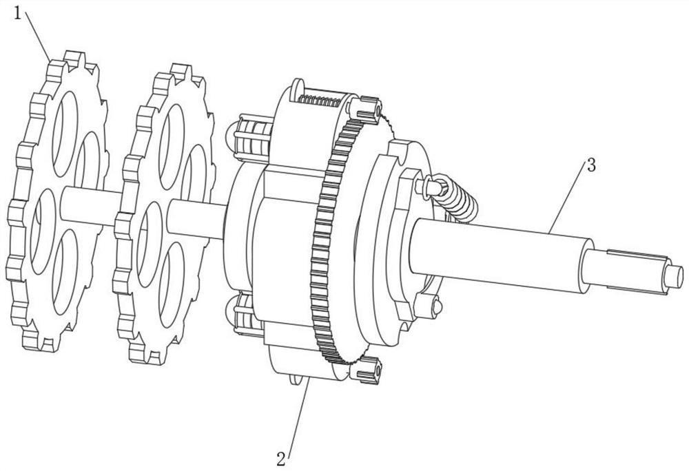
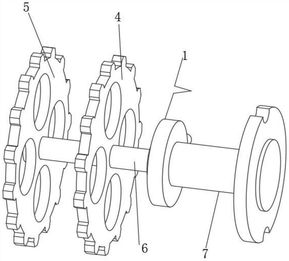
[0035] see Figure 1-9 , the present invention provides a technical solution: a push-type deceleration buffer adjustment structure, including a transmission device 1, the side end position of the transmission device 1 is sleeved with a restriction device 2, and the side end position of the restriction device 2 is sleeved with an adjustment device 3. By installing the transmission device 1, the transmission device 1 can be connected with the outside world to re...


PUM


Abstract

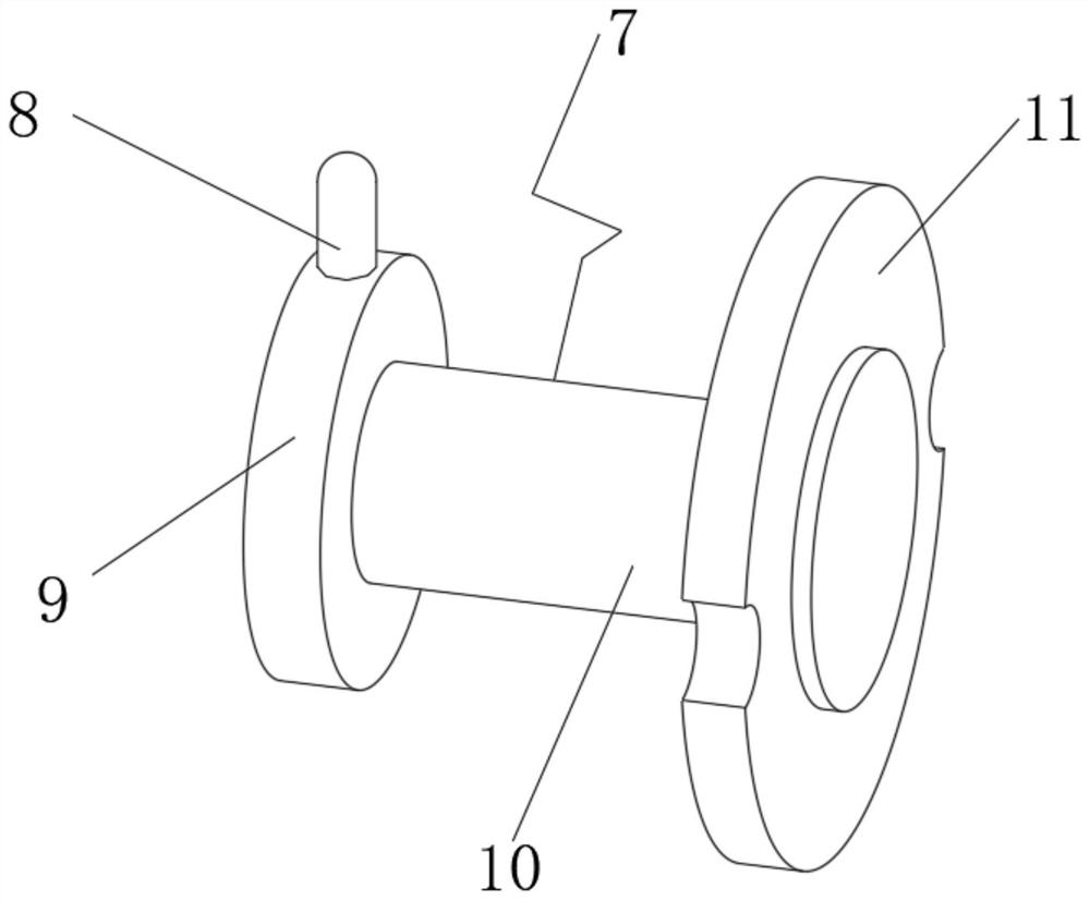
The invention discloses a push type deceleration buffer adjusting structure which comprises a transmission device, the side end position of the transmission device is sleeved with a limiting device, the side end position of the limiting device is sleeved with an adjusting device, the transmission device comprises a first piece tooth, a second piece tooth, a transmission shaft and a contact component, the second piece tooth is arranged on one side of an inner end of the transmission device, the transmission shaft is inserted into the center of the second piece tooth, the first piece tooth is inserted into the center of the transmission shaft, the bottom of the transmission shaft is sleeved with the contact component, the contact component comprises a limiting rod shaft, a first ring frame, a center rod and a second ring frame, the first ring frame is arranged on one side of an inner end of the contact component, the upper end of the first ring frame is fixedly connected with the limiting rod shaft, and the side end of the first ring frame is fixedly connected with the center rod. According to the push type deceleration buffer adjusting structure, the purpose of limiting movement of the inner end is achieved through the arrangement of the limiting device.

Description

technical field [0001] The invention relates to the technical field of mechanical equipment, in particular to a push-type deceleration buffer adjustment structure. Background technique [0002] According to Chinese Patent No. CN208919227U, the utility model relates to a deceleration structure in a spare tire support assembly, the deceleration structure assembly in the spare tire support assembly is installed in the automobile spare tire support assembly; the spare tire support assembly The deceleration structure includes: drive shaft, eccentric wheel, torque arm and pulley, the drive shaft passes through the eccentric wheel, the eccentric wheel drives the torque arm, and the pulley is driven to rotate through the torque arm. The corresponding position of the pulley is provided with pulley teeth, and the torque arm teeth and the pulley teeth form a pair of internal meshing gear pairs, and the number of torque arm teeth is one less than the number of pulley teeth. The utility...

Claims


Application Information

Patent Timeline
IPC IPC(8): F16H37/12F16H57/00F16F15/04
CPCF16H37/124F16H57/0006F16F15/04
Inventor 董盛融
Owner 欧亿光信息技术(太仓)有限公司
Learn More