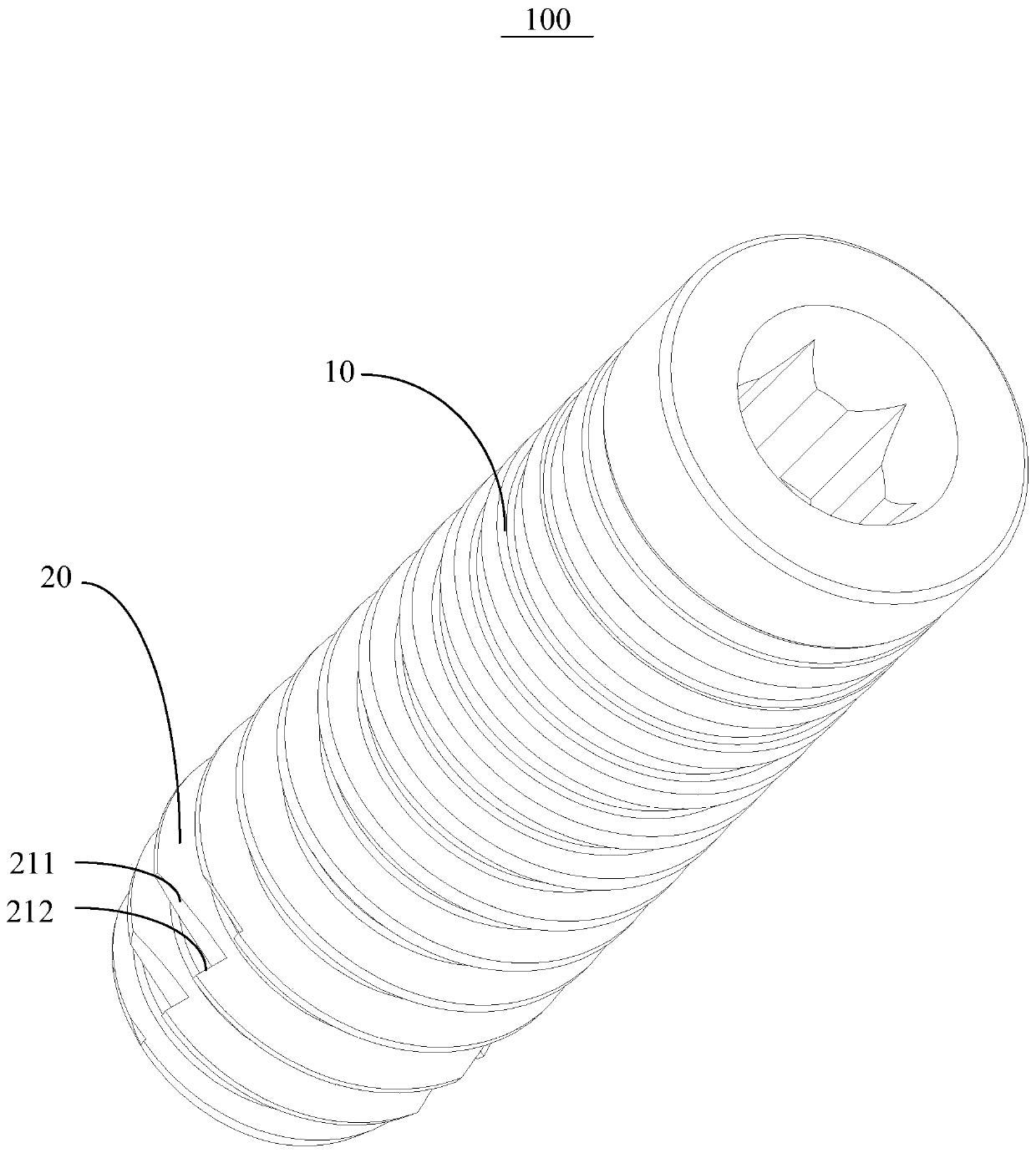
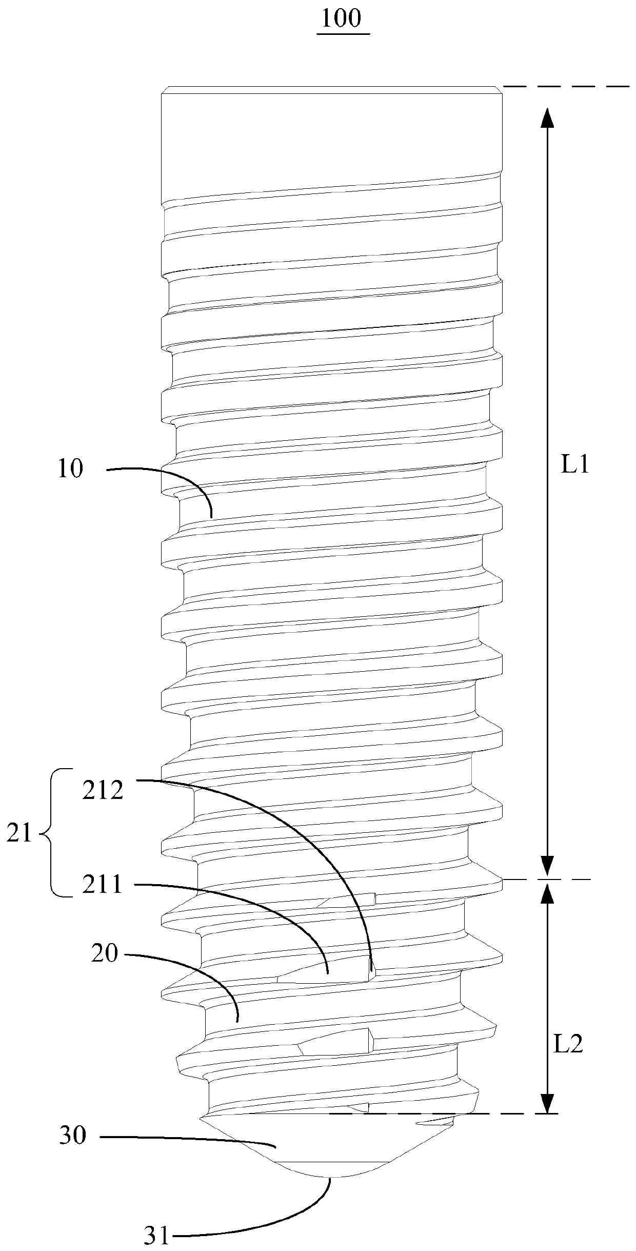
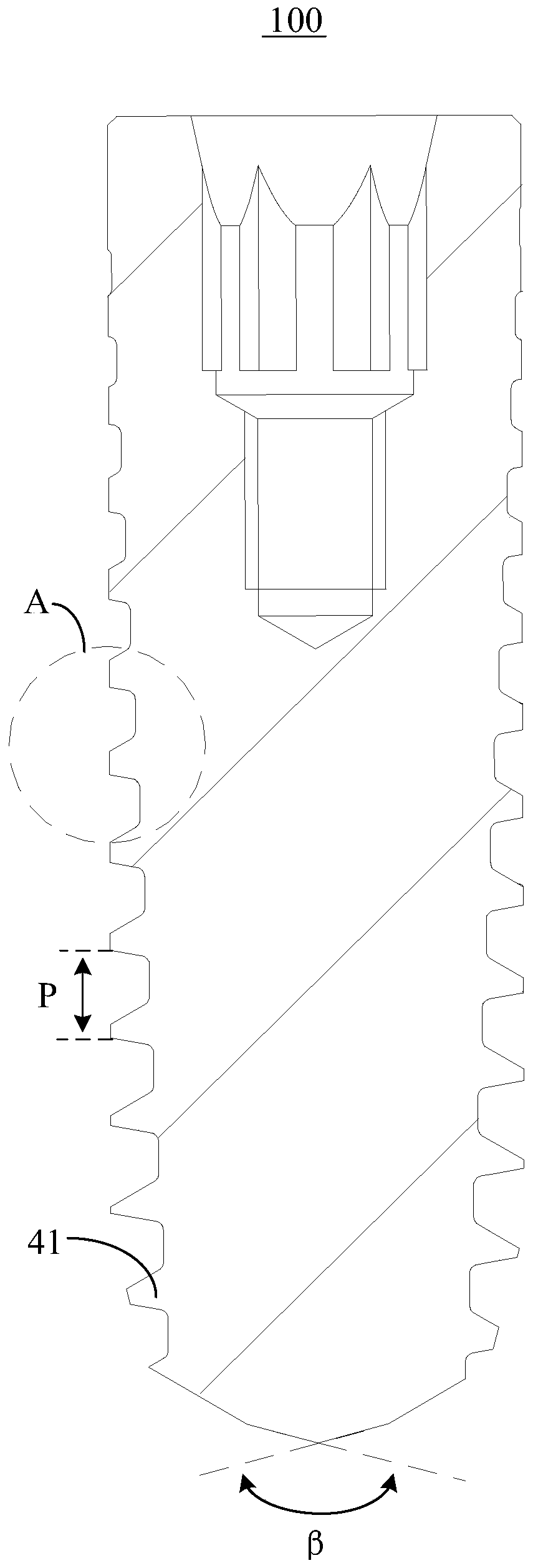
Dental implant

A technology of dental implants and tapered segments, applied in dentistry, dental implants, medical science, etc., can solve the problems of limited contact area of ​​artificial implants, slow formation of bone tissue, and few surface contact points, etc., to achieve firm loosening, The effect of increasing the attachment point and increasing the contact surface area

Pending Publication Date: 2019-08-09
广东安特齿科有限公司
View PDF0 Cites 0 Cited by
  • Summary
  • Abstract
  • Description
  • Claims
  • Application Information

AI Technical Summary

Problems solved by technology

Some existing implants are arranged in an inverted conical shape. Although this structure makes it easier for the artificial implant to be screwed into the alveolar bone, the screwing force is small, but the contact area between the artificial implant and the tooth bone is limited, and the surface c

Method used


Image

  • Dental implant
  • Dental implant
  • Dental implant

Examples


Embodiment Construction

[0027] The following will clearly and completely describe the technical solutions in the embodiments of the present invention with reference to the accompanying drawings in the embodiments of the present invention. Obviously, the described embodiments are only part of the embodiments of the present invention, not all of them. Based on the embodiments of the present invention, all other embodiments obtained by persons of ordinary skill in the art without creative efforts fall within the protection scope of the present invention.

[0028] It should be noted that all directional indications (such as up, down, left, right, front, back...) in the embodiments of the present invention are only used to explain the relationship between the components in a certain posture (as shown in the accompanying drawings). Relative positional relationship, movement conditions, etc., if the specific posture changes, the directional indication will also change accordingly.

[0029] In the present in...


PUM

PropertyMeasurementUnit
Pitchaaaaaaaaaa

Abstract

The invention discloses a dental implant. The dental implant comprises a cylindrical section, a conical section and a tail vertebra section; the conical section is connected with the cylindrical section, and the conicity of the conical section is gradually reduced in the direction away from the cylindrical section; the tail vertebra section is arranged at the end, away from the cylindrical section, of the conical section, the conicity angle formed by the tail vertebra section is greater than that formed by the conical section, and the outer surfaces of the cylindrical section and the conical section are provided with threaded parts. By means of the technical scheme, the contact area with the dental bone is increased, the stability of the dental implant after implanting is improved, and theoverall strength is ensured.

Description

technical field [0001] The invention relates to the technical field of medical instruments, in particular to a dental implant. Background technique [0002] In the process of dental implantation, a biocompatible metal artificial implant is usually implanted into the tooth bone where the tooth is missing. Through the tight combination of the artificial implant and the tooth bone, the artificial implant is used as the installation healing base. Bases for benches and crowns. Some existing implants are arranged in an inverted conical shape. Although this structure makes it easier for the artificial implant to be screwed into the alveolar bone, the screwing force is small, but the contact area between the artificial implant and the tooth bone is limited, and the surface contact point is too large. Less, the formation of bone tissue is slower, resulting in insufficient stability and easy loosening. If the thread depth is increased in order to improve stability, it will increase t...

Claims


Application Information

Patent Timeline
IPC IPC(8): A61C8/00
CPCA61C8/0024A61C8/0025
Inventor 王五星易传伟
Owner 广东安特齿科有限公司
Why Eureka
Try Eureka