
Automatic sandblasting device special for tire mold

A tire mold and sandblasting device technology, applied in the field of construction machinery, can solve the problems of mold shaking, affecting the aesthetics of the mold, and large adhesion, and achieving the effect of ensuring stability

Pending Publication Date: 2019-08-09
青岛申通达机械科技有限公司
View PDF0 Cites 3 Cited by
  • Summary
  • Abstract
  • Description
  • Claims
  • Application Information

AI Technical Summary

Problems solved by technology

[0005] The purpose of the present invention is to solve the shortcomings in the prior art, such as: the existing automatic sandblasting device for tire molds usually causes the mold to shake due to the impact force of the nozzle during the sandblasting process of the mold, and then causes the mold to be broken. Unstable, and after the sandblasting is completed, a large amount of gravel will always adhere to the surface of the mold, causing the surface of the mold to be untidy and affecting the aesthetics of the mold

Method used

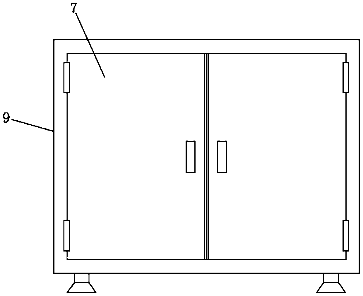
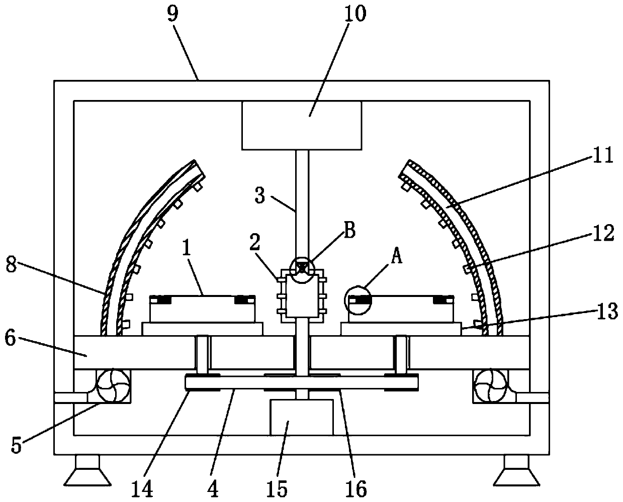
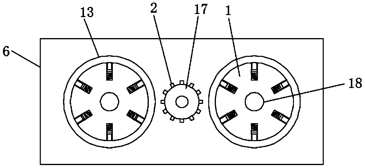

Image

  • Automatic sandblasting device special for tire mold
  • Automatic sandblasting device special for tire mold
  • Automatic sandblasting device special for tire mold

Examples


Embodiment Construction

[0024] The following will clearly and completely describe the technical solutions in the embodiments of the present invention with reference to the accompanying drawings in the embodiments of the present invention. Obviously, the described embodiments are only some, not all, embodiments of the present invention.

[0025] In describing the present invention, it should be understood that the terms "upper", "lower", "front", "rear", "left", "right", "top", "bottom", "inner", " The orientation or positional relationship indicated by "outside", etc. is based on the orientation or positional relationship shown in the drawings, and is only for the convenience of describing the present invention and simplifying the description, rather than indicating or implying that the referred device or element must have a specific orientation, so as to Specific orientation configurations and operations, therefore, are not to be construed as limitations on the invention.

[0026] refer to Figure ...


PUM


Abstract

The invention discloses an automatic sandblasting device special for a tire mold. The automatic sandblasting device comprises a shell; a mounting plate is fixedly mounted on the inner side wall of theshell; two workpiece placement platforms are symmetrically and rotationally connected to the upper end face of the mounting plate; the upper end face of each workpiece placement platform is fixedly connected with a workpiece fixing platform; a plurality of sliding cavities are formed in the upper end face of each workpiece fixing platform in the circumferential direction at equal intervals; and an electromagnet is transversely and fixedly mounted in each sliding cavity, a magnet exciting coil is wound on each electromagnet, and a permanent magnet is slidably connected into each sliding cavity. According to the automatic sandblasting device, in the sandblasting process of the mold, a controller controls a fan to be powered on, then the fan operates, air blasting is conducted on the surfaceof the mold through a sandblasting nozzle on the inner side of an air blasting pipe, and then sand gravel on the surface of the mold falls off from the surface of the mold quickly, so that the surface of the mold is cleaner and more attractive.

Description

technical field [0001] The invention relates to the technical field of construction machinery, in particular to an automatic sandblasting device for tire molds. Background technique [0002] The sandblasting machine is generally powered by compressed air. Through the negative pressure formed in the spray gun by the high-speed movement of the air flow, the abrasive is sucked into the spray gun through the sand delivery pipe and ejected through the nozzle to the surface to be processed to achieve the desired processing purpose. In the suction type dry sandblasting machine, the compressed air is not only the feeding power but also the acceleration power of the jet. The abrasive is sprayed at high speed to the surface of the workpiece to be processed for impact grinding, so that the shape or shape of the outer surface of the workpiece surface changes. Due to the abrasive The impact and cutting action on the surface of the workpiece, the surface of the workpiece obtains a certain...

Claims


Application Information

Patent Timeline
Patent Type & Authority Applications(China)
IPC IPC(8): B24C3/22B24C9/00
CPCB24C3/22B24C9/00
Inventor 闫亚运王兆志隋新政
Owner 青岛申通达机械科技有限公司
Learn More