
Assembling clamp and device for inner sealing ring of clamping pipe

A technology of inner sealing ring and assembly fixture, which is applied in the direction of manufacturing tools and hand-held tools, etc., can solve the problems of low production efficiency and slow installation speed, and achieve the effect of improving installation efficiency and simplifying the installation process

Pending Publication Date: 2019-08-09
GUANGDONG UNIV OF TECH +1
View PDF0 Cites 2 Cited by
  • Summary
  • Abstract
  • Description
  • Claims
  • Application Information

AI Technical Summary

Problems solved by technology

However, for some small pipes, such as 4-point and 6-point pipes for household use, it is usually difficult for operators to directly insert their fingers into the pipe. At the same time, the diameter of the sealing ring is larger than the opening size of the nozzle. Therefore, it is necessary to reduce the diameter of the sealing ring or It can be installed into the pipeline after twisting, resulting in slow installation speed and low production efficiency.

Method used


Image

  • Assembling clamp and device for inner sealing ring of clamping pipe
  • Assembling clamp and device for inner sealing ring of clamping pipe
  • Assembling clamp and device for inner sealing ring of clamping pipe

Examples


Embodiment 1

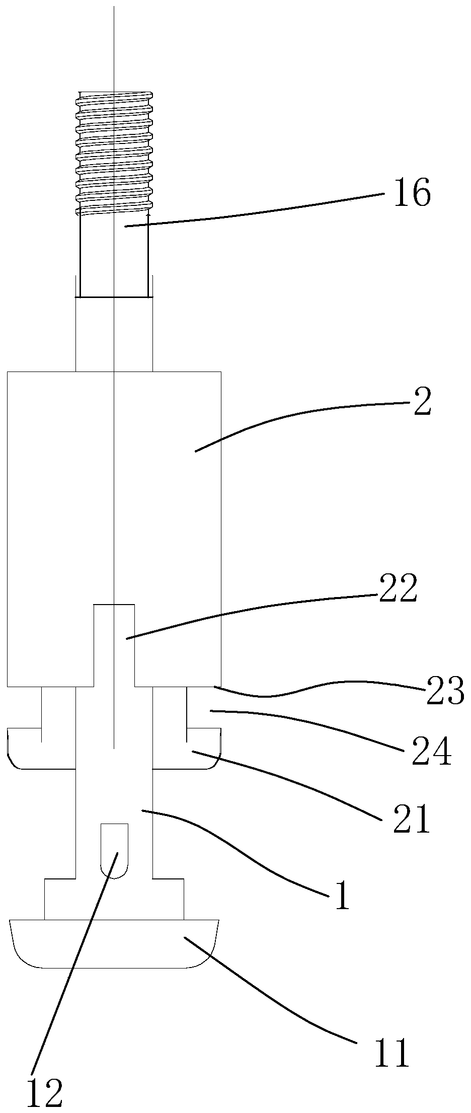
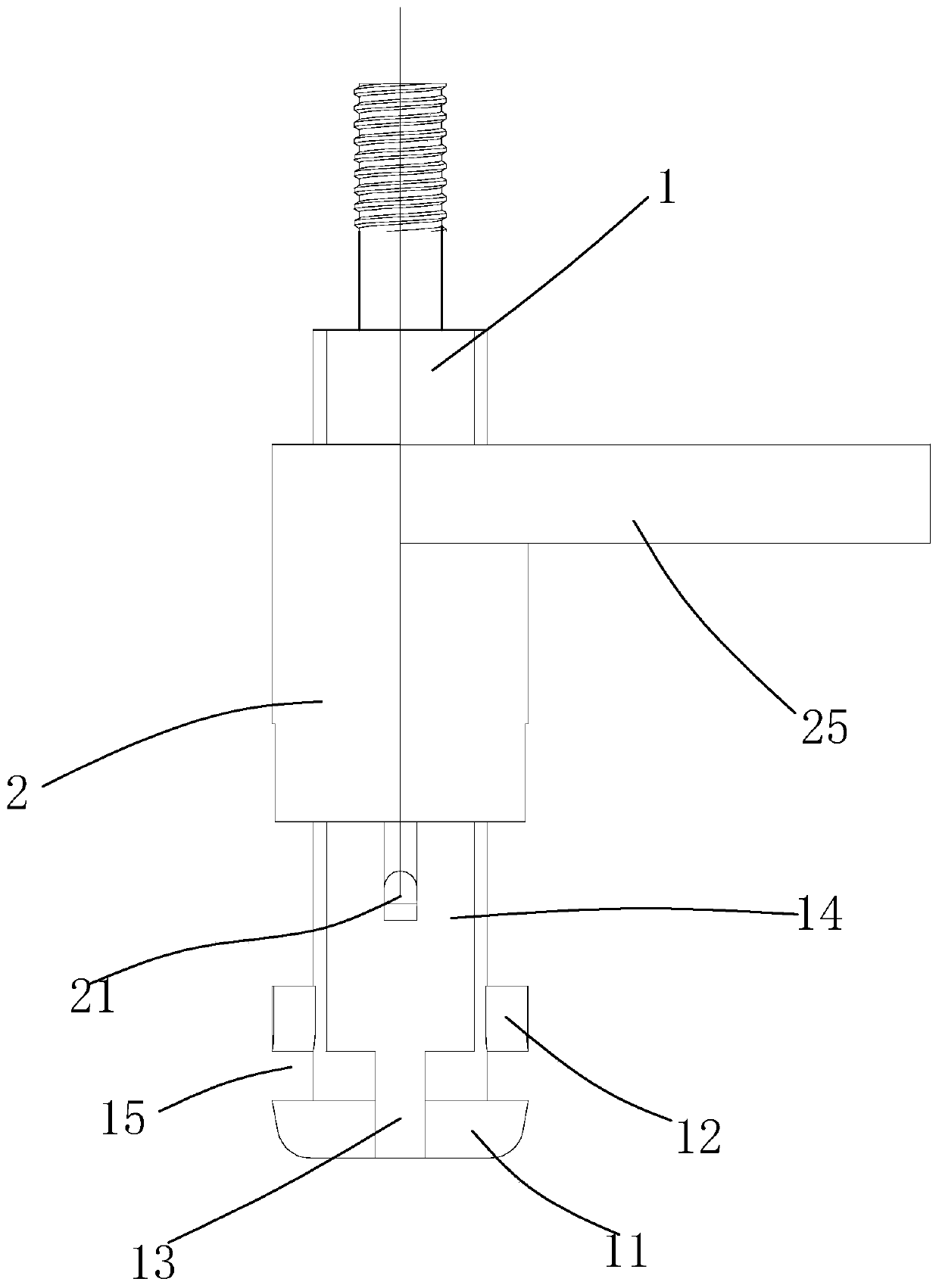
[0024] Embodiment one: refer to Figure 1 ~ Figure 2 , a jig for assembling an inner sealing ring of a pressed tube, comprising a push rod 1 and a sleeve 2, the sleeve 2 includes a cavity, and the upper end of the push rod 1 is inserted into the cavity of the sleeve, so The bottom of the push rod 1 includes a bottom plate 11, and the lower end of the push rod is provided with two opposite first hooks 12, and there is a gap 15 between the first hooks 12 and the bottom plate 11, and the sleeve 2 Two second hooks 21 opposite to each other are provided at the bottom, and the planes where the first hook 12 and the second hook 21 are located are perpendicular to each other. The sleeve 2 includes a bottom surface 23, and there is a gap 24 between the second hook and the bottom surface.

[0025] When working, the casing and the push rod are relatively separated by a certain distance, so that the first hook and the second hook form a certain height difference on the vertical plane, an...

Embodiment 2

[0026] Embodiment 2: In addition to four hooks, there may be two hooks, one for the first hook and one for the second hook, and the phase angle difference between the projections of the two hooks on the horizontal plane is about 180°. Since the two hooks are not located at the same projection position, when the relative positions of the two hooks change, the inner sealing ring can be stretched and deformed, so that the inner sealing ring can be hung on the two hooks. However, since there are only two hooks, a greater height difference is required to allow the inner sealing ring to generate enough elasticity to hang on the hooks when stretching.

[0027] Regardless of the above-mentioned embodiment, as a further preferred embodiment, the bottom plate 11 is provided with a through groove 13, and the through groove 13 is located directly below the second hook 21; the bottom of the sleeve 2 is provided with The notch 22 is located right above the first hook 12 .

[0028]As a furt...


PUM


Abstract

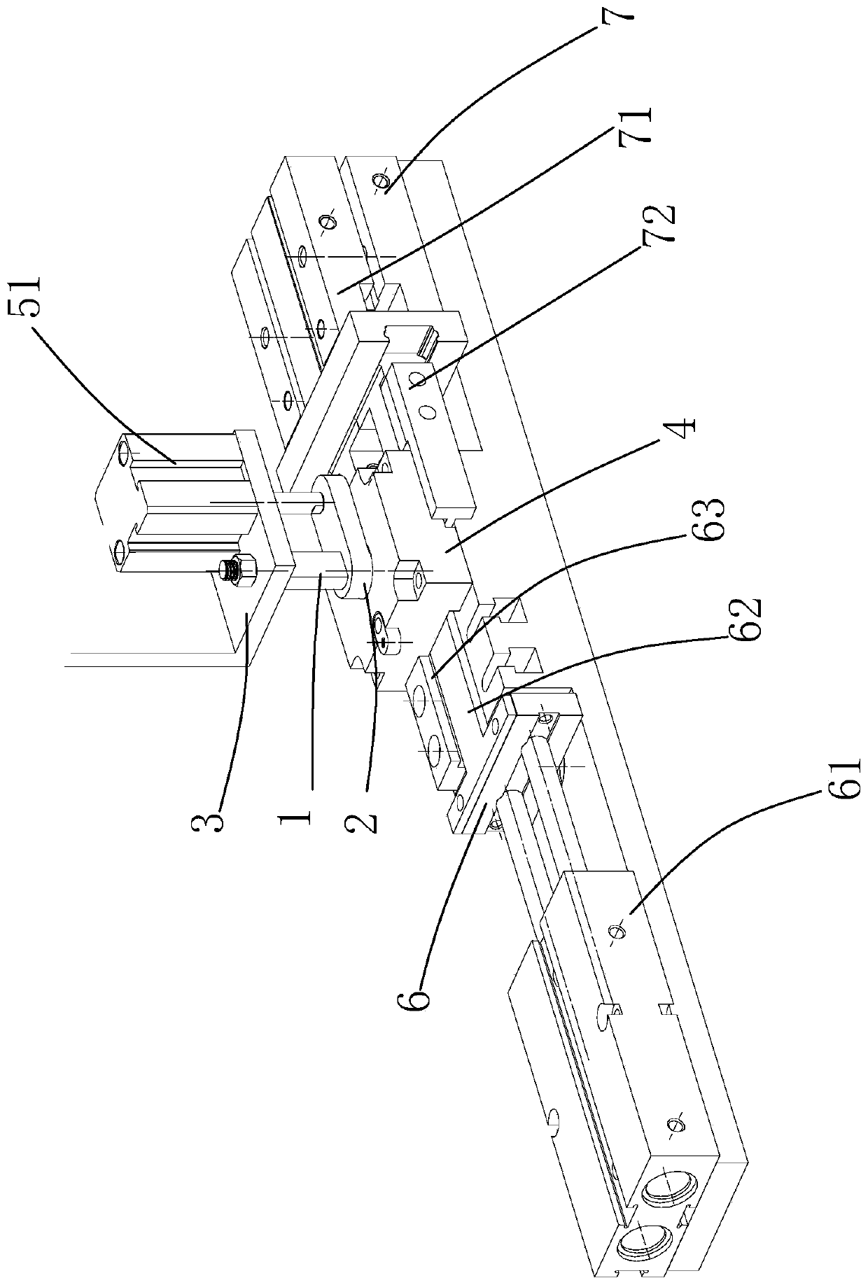
The invention discloses an assembling clamp for an inner sealing ring of a clamping pipe. The assembling clamp comprises a push rod and a sleeve, wherein the bottom of the push rod comprises a bottomplate; a first hook is arranged at the lower end of the push rod; a second hook is arranged at the bottom of the sleeve; and the first hook and the second hook are positioned on different projection surfaces. The sealing ring sleeved in the clamp can realize the tensile deformation by utilizing the first hook on the push rod and the second hook on the sleeve. Meanwhile, the invention also providesan assembling device for the inner sealing ring of the clamping pipe. The device comprises the clamp, a mounting seat and a base, wherein a driving mechanism is arranged on the mounting seat; the base comprises a through hole; and the front end of the base is provided with a feeding mechanism, and the left side and the right side of the base are provided with clamping mechanisms. By mounting theclamp in an automatic device, the assembly of the inner sealing ring can be automatic, and the production efficiency is greatly improved.

Description

technical field [0001] The invention relates to automatic equipment, in particular to automatic assembly equipment for inner sealing rings. Background technique [0002] In the direct drinking water system, tap water system, heating system, steam system, industrial oil pipe system and other piping systems, the connection of the connecting pipe body will be used at the turning point. Usually, the connection between the connecting pipe body and the pipe fittings adopts threaded or welded connection forms, but These connection methods are cumbersome to operate, have low efficiency, and are prone to loosening and leakage in an environment with frequent vibrations. The working principle of the compression fitting is to insert a thin-walled stainless steel tube into the socket of the compression fitting, and use a special compression tool to clamp the stainless steel tube in the fitting. The section shape of the compression part is hexagonal. The sealing structure is set between ...

Claims


Application Information

Patent Timeline
Patent Type & Authority Applications(China)
IPC IPC(8): B25B27/02
CPCB25B27/02
Inventor 程永奇陈宇航何腾功容刚
Owner GUANGDONG UNIV OF TECH
Learn More