Braking device and method of mechanically driven road roller

A technology of mechanical drive and braking device, which is applied in the direction of foot-operated starting device, braking transmission device, mechanical control, etc., and can solve the problems of being unable to cut off the power and prone to danger

Pending Publication Date: 2019-08-09
XCMG CONSTR MACHINERY
View PDF0 Cites 0 Cited by
  • Summary
  • Abstract
  • Description
  • Claims
  • Application Information

AI Technical Summary

Problems solved by technology

[0004] The purpose of the present invention is to solve the problem that the power cannot be cut off when the brake pedal is directly stepped on when the mechanically driven road roller is in emergency braking, which is prone to danger

Method used


Image

  • Braking device and method of mechanically driven road roller
  • Braking device and method of mechanically driven road roller
  • Braking device and method of mechanically driven road roller

Examples


Embodiment Construction

[0027] The present invention will be further described below in conjunction with the accompanying drawings. The following examples are only used to illustrate the technical solution of the present invention more clearly, but not to limit the protection scope of the present invention.

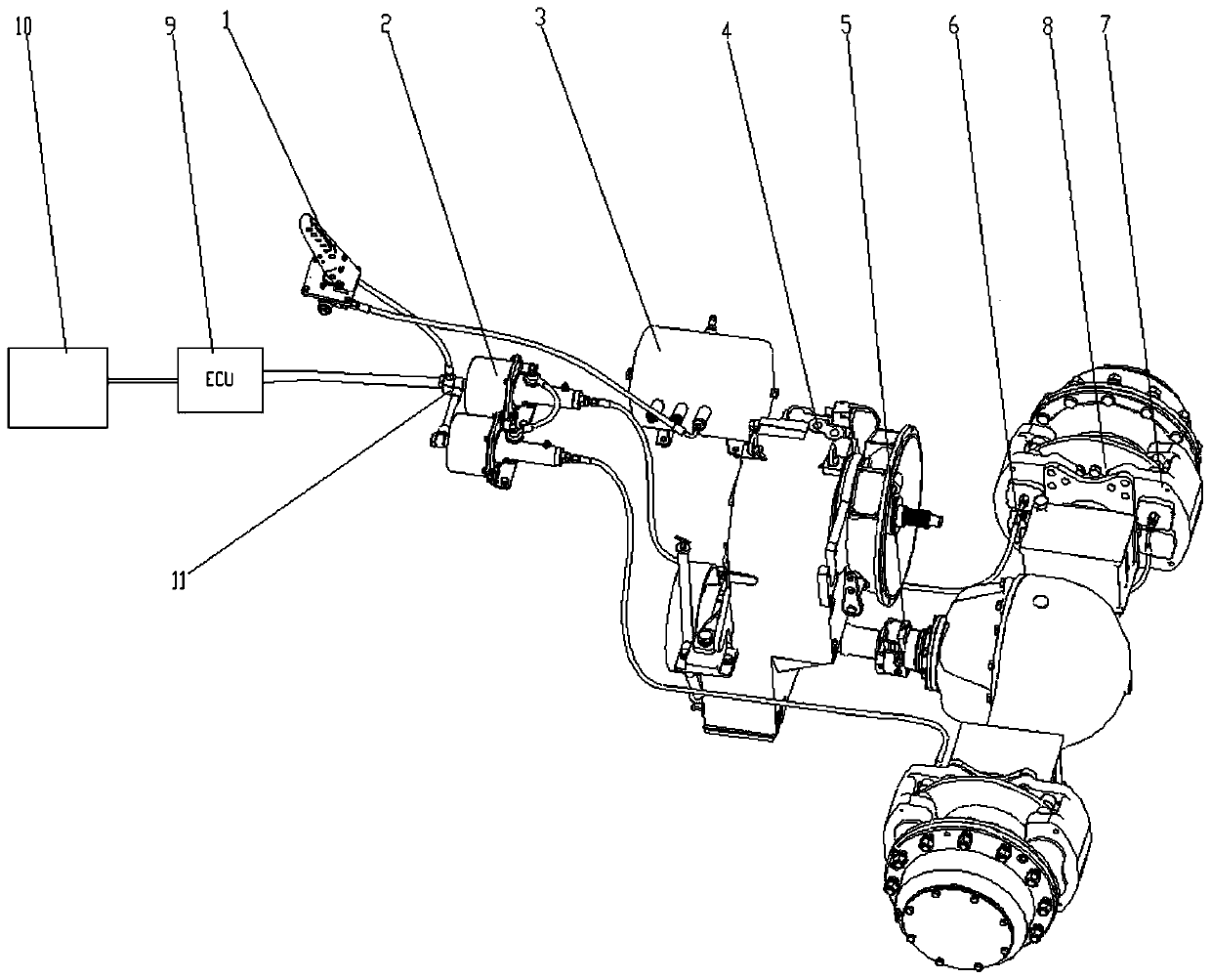
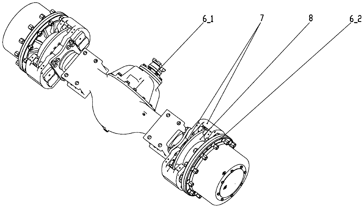
[0028] Such as figure 1 and image 3 As shown, the brake pedal 1, the air booster pump 2, the air bag 3, the mechanical gearbox 4, the drive axle 6, the ECU controller 9, and the engine 10 are installed in the appropriate parts of the mechanically driven road roller, and the transmission shaft 5 is connected to the mechanical gearbox 4 The output terminal of the driving bridge 6 and the driving bridge input terminal 6_1 of the driving bridge 6 . Brake disc 8 is welded as one with wheel edge mounting disc 6_2, and when transaxle input end 6_1 has rotational torque input, brake disc 8 and wheel limit mounting disc 6_2 rotate synchronously. Brake 7 is fixed on the drive axle 6 wheel housings by ...


PUM


Abstract

The invention discloses a braking device and method of a mechanically driven road roller. An air pocket is manipulated by a braking pedal to convey air to an air booster pump; when a piston of the airbooster pump is under the air pressure, braking fluid is pushed into a brake for braking; an air booster pump input pressure signal collected by an air pressure sensor is transmitted to an ECU controller; and the ECU controller controls an engine to lower the output torque according to the pressure signal transmitted by the air pressure sensor, thus the braking torque of the brake is larger thanthe output torque of the engine, and the engine is subjected to flameout braking. The braking problem of the mechanically driven road roller can be solved, during braking, a driver only needs to treadthe braking pedal and does not need to tread a clutch pedal simultaneously, then quick braking can be achieved, and the braking time and the braking distance are shortened.

Description

technical field [0001] The invention relates to a braking device and a braking method of a mechanically driven road roller, belonging to the technical field of road rollers. Background technique [0002] The power and transmission chain of the mechanically driven road roller are mainly composed of engine, gearbox, transmission shaft, drive axle and other components. When the mechanically driven road roller brakes, the driver directly steps on the brake pedal. At this time, the brake acts on the side of the drive axle to prevent the drive axle from rotating, but at this time the drive chain still transmits power to make the drive axle continue to rotate, that is, braking When the power cannot be cut off. [0003] At present, in the industry, there are mainly two types of gearboxes for mechanically driven road rollers. One is electronically controlled gearboxes. Electronically controlled gearboxes control the on and off of solenoid valves through electrical signals, and then ...

Claims


Application Information

Patent Timeline
Patent Type & Authority Applications(China)
IPC IPC(8): B60T7/04B60T13/36F02D29/02F02D17/04F02D41/04E01C19/26
CPCB60T7/04B60T13/36E01C19/26F02D17/04F02D29/02F02D41/042F02D2200/1002F02D2700/07
Inventor 孟绪周保刚何明虎张帅王双亢涛宋晓瑞杨锋
Owner XCMG CONSTR MACHINERY
Why Eureka
Try Eureka