
Steel arch frame closure device

A technology of steel arches and telescopic devices, applied in the field of steel arches, which can solve problems such as the inability to automatically adjust the arc length of steel arches, and achieve the effects of convenient and quick adjustment, good versatility, and high rigidity

Pending Publication Date: 2019-08-09
CHONGQING BIAOWANG MACHINERY EQUIP CO LTD
View PDF1 Cites 0 Cited by
  • Summary
  • Abstract
  • Description
  • Claims
  • Application Information

AI Technical Summary

Problems solved by technology

Although the steel arch closing and unloading device can realize the arch closing, it cannot automatically adjust the arc length of the steel arch

Method used


Image

  • Steel arch frame closure device
  • Steel arch frame closure device
  • Steel arch frame closure device

Examples


Embodiment 1

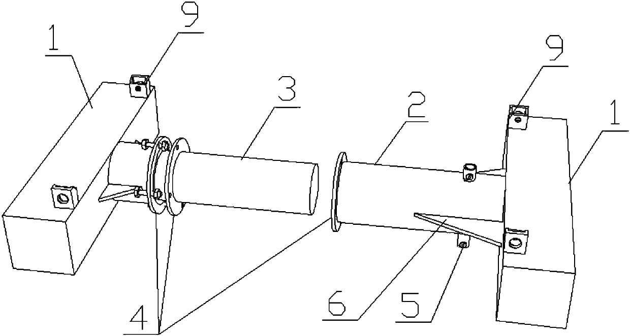
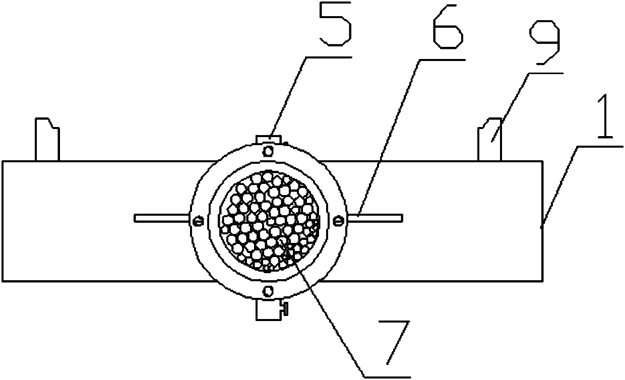
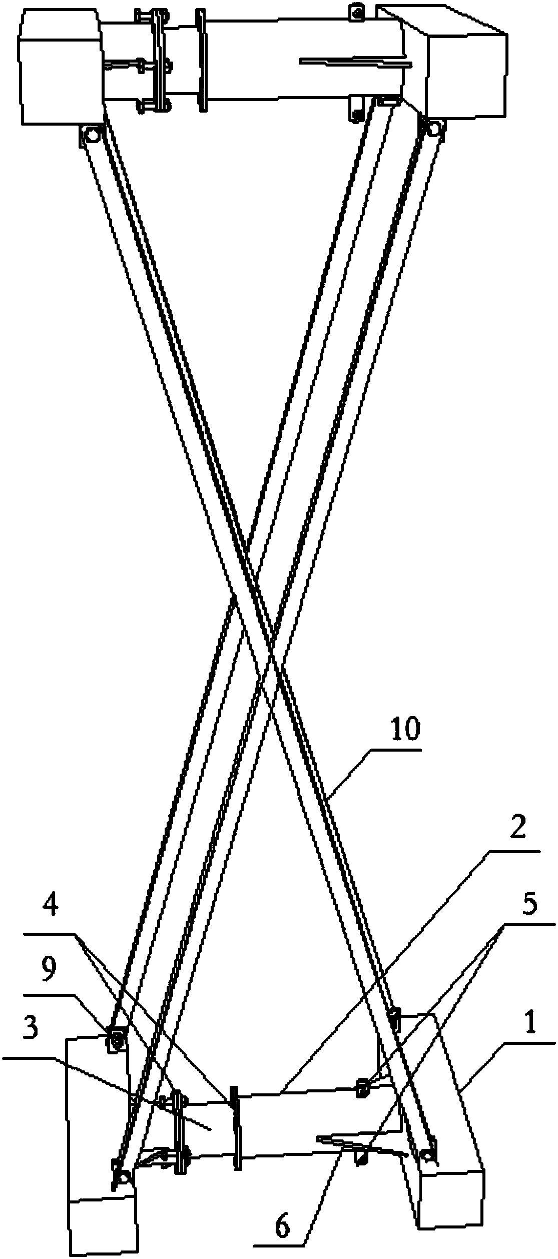
[0028] A steel arch closing device, such as Figure 1 to Figure 3 As shown, it includes an upper chord and a lower chord, and a support 10 is arranged between the upper chord and the lower chord, and a telescopic device for adjusting the length of the upper chord and the lower chord. The telescopic device adopts a flexible telescopic device to realize the stroke adjustment of the steel arch closing device. The flexible telescopic device includes a cylinder body 2 and a telescopic rod 3. The telescopic rod 3 extends into the cylinder body 2 and forms a space for accommodating the steel ball sand 7 with the inner wall of the cylinder body 2. The telescopic rod 3 moves axially along the cylinder body 2 to extrude the steel ball sand 7. Realize telescopic adjustment. Through the mutual cooperation of the steel ball sand 7, the telescopic rod 3 and the cylinder body 2, the automatic shrinkage of the flexible telescopic device can be realized to adjust the stroke of the steel arch c...

Embodiment 2

[0042] A steel arch closing device, such as Figure 5 As shown, it includes the upper chord and the lower chord, and there is a support between the upper chord and the lower chord, and two sets of telescopic devices for adjusting the length of the upper chord and / or the lower chord. The telescopic device adopts a flexible telescopic device to realize the stroke of the steel arch closing device adjust. The flexible telescopic device includes a cylinder body and a telescopic rod. The telescopic rod extends into the cylinder body and forms a space for accommodating the steel ball sand with the wall of the cylinder body. The telescopic rod moves along the axial direction of the cylinder body to squeeze the steel ball sand to realize telescopic adjustment. The automatic contraction of the flexible telescopic device can be realized through the mutual cooperation of the steel ball sand, the telescopic rod and the cylinder to adjust the stroke length of the steel arch closing device, ...

Embodiment 3、 Embodiment 4

[0051] A closing segment, using the steel arch closing device in Embodiment 1 or Embodiment 2 respectively.


PUM


Abstract

The invention provides a steel arch frame closure device. The steel arch frame closure device comprises an upper chord and a lower chord and a telescopic device, wherein the telescopic device is usedfor adjusting the length of the upper chord and / or the lower chord; the telescopic device adopts a flexible telescopic device to adjust the travel of the steel arch frame closure device, wherein the flexible telescopic device comprises a cylinder body and a telescopic rod; the telescopic rod extends into a cylinder body to form a space, for accommodating steel ball sand, together with the cylinderbody wall; and a telescopic rod moves in the axial direction of the cylinder body to extrude the steel ball sand to realize telescopic adjustment. According to the steel arch frame closure device, through coordination of the steel ball sand, the telescopic rod and the cylinder body, automatic retraction of the flexible telescopic device is realized to adjust the travel of the steel arch frame closure device so as to achieve the purpose of automatically adjusting the length of a steel arch frame arc; the steel arch frame arc length adjusting difficulty can be greatly reduced, and moreover, thesteel arch frame arc length can be automatically adjusted to guarantee that the steel arch frame arc satisfies requirements of a reinforced concrete main arch ring arc.

Description

technical field [0001] The invention relates to a steel arch, in particular to a closing device for a steel arch. Background technique [0002] In the field of arch bridge construction, the steel arch frame is the most important special support in the construction process of the entire cast-in-place reinforced concrete main arch ring, and it has extremely important significance for the cast-in-situ molding of the reinforced concrete main arch ring. [0003] The closing of the steel arch is the key process and key process of the steel arch installation. The existing steel arch installation is usually closed at the top of the steel arch. The closing method is mainly directly cutting according to the actual size of the site, assembling parts and welding. , the disadvantage is that it is difficult to process the relevant parts used in the cage part on site, and the processing accuracy is poor, which will easily lead to the stress concentration of the upper and lower chords of th...

Claims


Application Information

Patent Timeline
Patent Type & Authority Applications(China)
IPC IPC(8): E01D21/00E01D4/00E01D101/30
CPCE01D21/00E01D4/00E01D2101/30
Inventor 王华才张有德王沁薰贺之萱杨娴
Owner CHONGQING BIAOWANG MACHINERY EQUIP CO LTD
Learn More