Adjustable lock catch of storage rack
A storage rack and adjustable technology, applied in the direction of friction-clamping detachable fasteners, connecting components, furniture parts, etc., can solve the problems of only being installed on a fixed pipe diameter, unable to adjust the tightness, and poor fit. , to achieve the effect of simple structure, stable structure and function, and precise adjustment.
- Summary
- Abstract
- Description
- Claims
- Application Information
AI Technical Summary
Problems solved by technology
Method used
Image
Examples
Embodiment 1
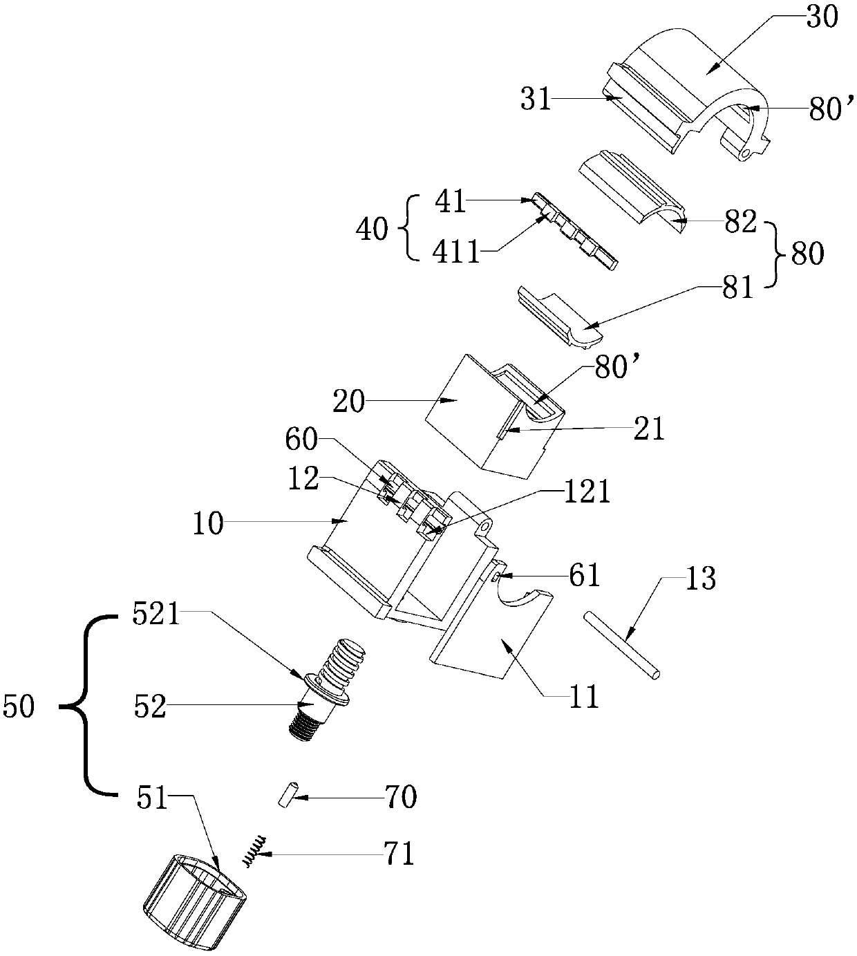
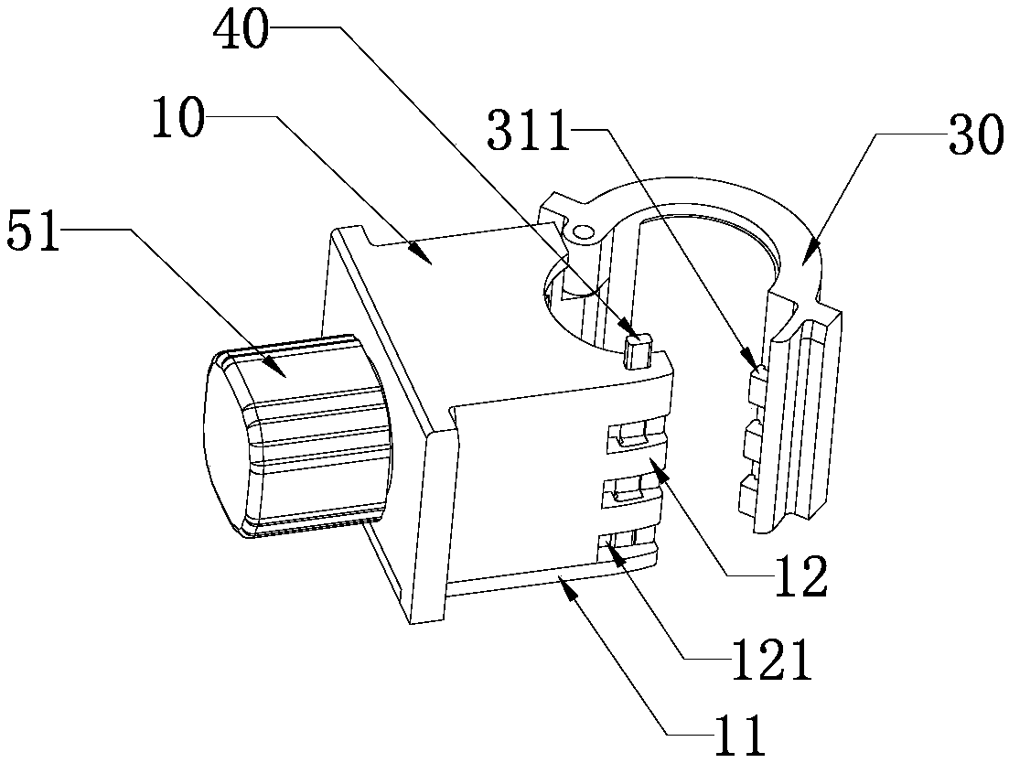
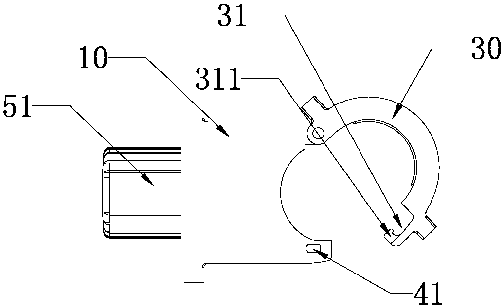
[0039] like Figure 1 to Figure 7 As shown, an adjustable buckle of a storage rack is used to lock and cooperate with a shower rod, including a base 10, a left half ring 20, a right half ring 30 and a locking device 40; the base 10 One end is hinged with one side of the right half of the ring 30; the side of the right half of the ring 30 away from the hinge with the base 10 is provided with a first engaging portion 31; The hinged side of the right half ring 30 is provided with a second engaging portion 12; the right half ring 30 and the base 10 pass through the first engaging portion 31 and the second engaging portion engaging and locking by the locking device 40; the base 10 is provided with an accommodating cavity for accommodating the left half embracing ring 20; the left half embracing ring 20 is accommodated in the accommodating cavity, It also includes an adjustment mechanism 50 that can make the left half wrap 20 approach or move away from the right half wrap 30 .
[...
Embodiment 2
[0051] like Figure 8 to Figure 12 As shown, the difference between this embodiment and the first embodiment is that the locking device 40' includes an elastic member and a second locking bolt 41'; the elastic member is a second spring 42; the second locking bolt 41' is provided with a second locking block 411' that engages with the protrusion 311; the base 10 is engaged with the right half ring 30 to form a second locking groove 60' with a closed top; Both ends of the elastic member abut against the top ends of the second locking bolt 41' and the second locking groove 60' respectively, so that the second locking bolt 41' can elastically reciprocate and slide in the locking groove 60' , and then drive the second locking block 411 ′ to engage with or separate from the slot of the protruding block 311 .
[0052] In this embodiment, the second locking block 411' has a guiding slope, which is convenient for pressing the second locking bolt 41' through the guiding slope when the r...
Embodiment 3
[0055] like Figure 13 to Figure 15 As shown, the difference between this embodiment and the first embodiment is that it also includes a rack body 1, the rack body 1 is provided with a bracket, the inner wall of the bracket is provided with a number of slots 1b, and the base 10. The outer wall of 10 is correspondingly provided with a plug-in rib 15 that is plugged and matched with the slot 1b, and the bottom of the bracket is provided with a snap-in part 1a. Specifically, the snap-in part 1a adopts a pit structure or a snap-in connection. Hole structure, the bottom of the base is correspondingly provided with a buckle 14 that is engaged with the buckle part 1a, so that the installation structure between the lock buckle and the rack body 1 is simple, reliable, and easy to operate.
PUM
 Abstract
Description
Claims
Application Information
 - R&D
- Intellectual Property
- Life Sciences
- Materials
- Tech Scout
- Unparalleled Data Quality
- Higher Quality Content
- 60% Fewer Hallucinations
Browse by: Latest US Patents, China's latest patents, Technical Efficacy Thesaurus, Application Domain, Technology Topic, Popular Technical Reports.
© 2025 PatSnap. All rights reserved.Legal|Privacy policy|Modern Slavery Act Transparency Statement|Sitemap|About US| Contact US: help@patsnap.com


