Probe-based rotating shaft rotation center line geometric error calibration method

A center of rotation and geometric error technology, applied in the field of error compensation, can solve the problems that are not suitable for five-axis non-contact measuring machines, and achieve the effects of avoiding installation errors, simple installation process, and clear calibration process

Active Publication Date: 2019-08-09
BOZHON PRECISION IND TECH CO LTD
View PDF10 Cites 10 Cited by
  • Summary
  • Abstract
  • Description
  • Claims
  • Application Information

AI Technical Summary

Problems solved by technology

At present, although there are some calibration methods for the geometric error of the rotation center of the rotary axis, these methods are mostly b

Method used


Image

  • Probe-based rotating shaft rotation center line geometric error calibration method
  • Probe-based rotating shaft rotation center line geometric error calibration method
  • Probe-based rotating shaft rotation center line geometric error calibration method

Examples


Example Embodiment

[0018] Example 1

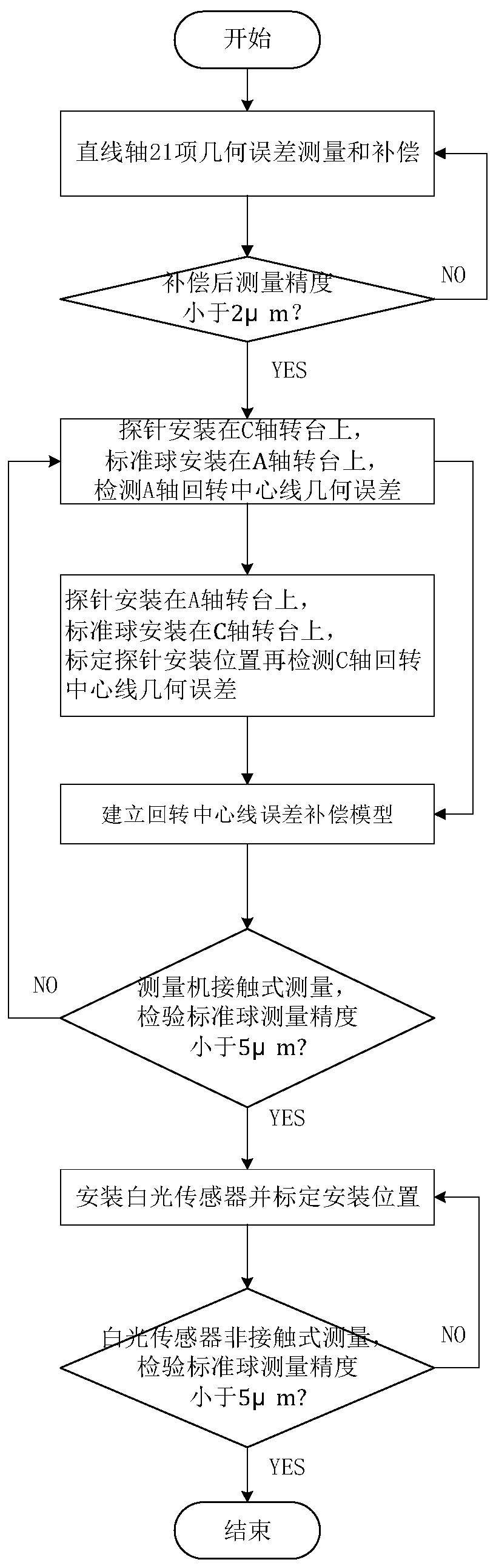
[0019] Such as figure 1 As shown, this embodiment includes the following steps:

[0020] Step S1, linear axis measurement accuracy compensation: measure and compensate 21 geometric errors of the three linear axes in the five-axis non-contact measuring machine; and use the body diagonal method to verify the linear axis error compensation results to ensure The comprehensive accuracy is less than 2μm;

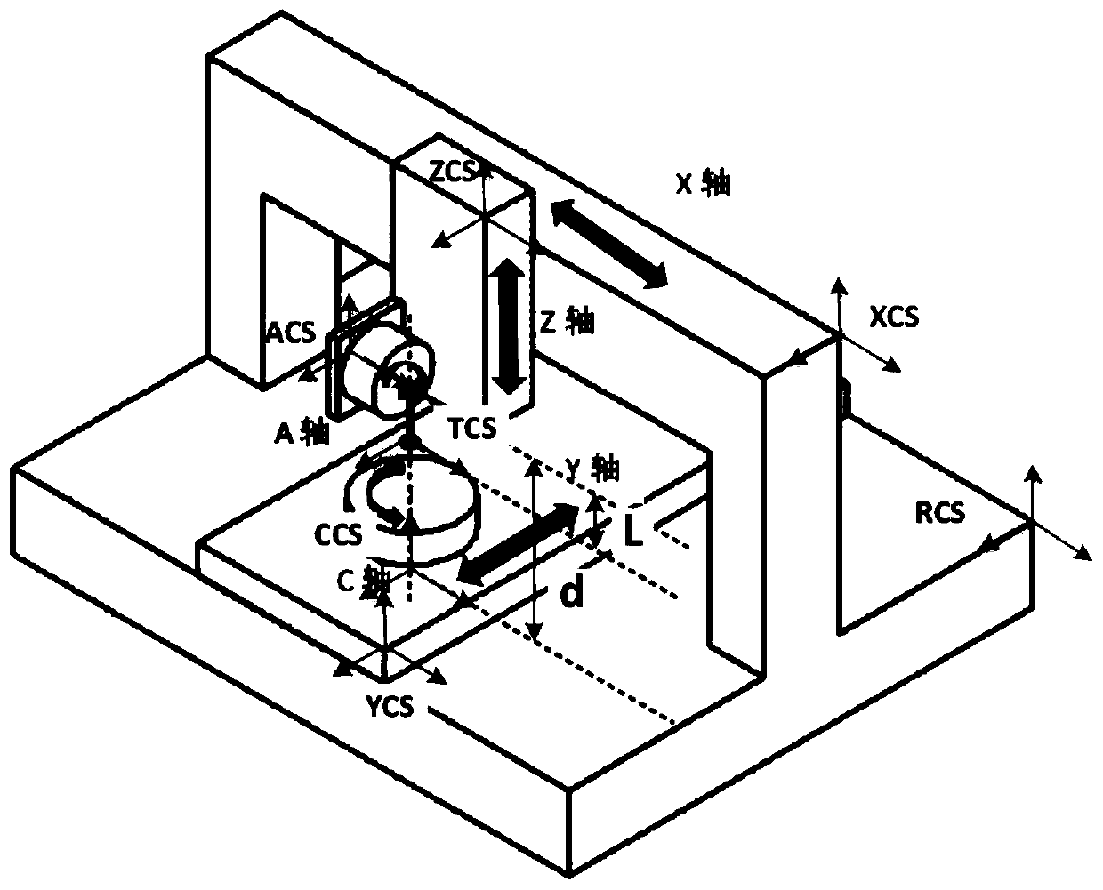
[0021] Step S2, establish the error compensation model of the rotation center line: After completing the operation in step S1, install the probe on the C-axis turntable or Y-axis, install the standard ball on the A-axis turntable, and check that the standard ball follows the A-axis turntable. The center of the circular motion obtains the geometric error of the A-axis rotation centerline; then the base coordinate system of the measuring machine is established with the center of the A-axis turntable working surface as the coordinate origin, the probe is installed on th...


PUM


Abstract

The invention discloses a probe-based rotating shaft rotation center line geometric error calibration method, and belongs to the technical field of measurement error compensation. The probe-based rotating shaft rotation center line geometric error calibration method comprises the following steps of S1, compensating the measurement accuracy of a linear shaft, S2, establishing a rotation center lineerror compensation model and S3, geometric error calibration of a rotation center line. The probe-based rotating shaft rotation center line geometric error calibration method is simple in measuring flow, is helpful for measuring machine development engineers and end users to quickly find out errors of the rotation center line, and the measuring accuracy is improved.

Description

technical field [0001] The invention relates to a technology in the field of error compensation, in particular to a probe-based method for calibrating the geometric error of the rotation centerline of a rotating shaft. Background technique [0002] Five-axis non-contact measuring machine, models such as figure 2 As shown, it integrates five-axis linkage and non-contact measurement, and provides a complete solution for the non-contact measurement requirements of complex curved surfaces / heterogeneous surfaces. This type of equipment is mainly used in auto parts, aircraft engine parts, mobile phones 3D glass, precision molds and other fields can provide measurement requirements such as dimension measurement and 3D dimension cloud image construction. [0003] Measurement accuracy is an important performance index of five-axis non-contact measuring machine, and the geometric error of the measuring machine accounts for more than 50% of the overall error of the whole machine. The...

Claims


Application Information

Patent Timeline
IPC IPC(8): G01B11/00G01B11/24
CPCG01B11/00G01B11/005G01B11/24
Inventor 史文浩孟健于福翔陈良锋史军新
Owner BOZHON PRECISION IND TECH CO LTD
Why Eureka
Try Eureka