
A RFID positioning method and device based on phase difference correction

A positioning method and phase difference technology, applied in the field of data processing, can solve the problems of phase measurement value offset, affecting actual accuracy, etc.

Active Publication Date: 2020-12-04
FOSHAN SHUNDE SUN YAT SEN UNIV RES INST +2
View PDF4 Cites 0 Cited by
  • Summary
  • Abstract
  • Description
  • Claims
  • Application Information

AI Technical Summary

Problems solved by technology

However, in practical applications, there will be coupling effects between adjacent RFID tags, which will cause the phase measurement value to shift, thus affecting the actual accuracy.

Method used


Image

  • A RFID positioning method and device based on phase difference correction
  • A RFID positioning method and device based on phase difference correction
  • A RFID positioning method and device based on phase difference correction

Examples


Embodiment Construction

[0048] This part will describe the specific embodiment of the present invention in detail, and the preferred embodiment of the present invention is shown in the accompanying drawings. Each technical feature and overall technical solution of the invention, but it should not be understood as a limitation on the protection scope of the present invention.

[0049] In the description of the present invention, it should be understood that the orientation descriptions, such as up, down, front, back, left, right, etc. indicated orientations or positional relationships are based on the orientations or positional relationships shown in the drawings, and are only In order to facilitate the description of the present invention and simplify the description, it does not indicate or imply that the device or element referred to must have a specific orientation, be constructed and operated in a specific orientation, and thus should not be construed as limiting the present invention.

[0050] I...


PUM


Abstract

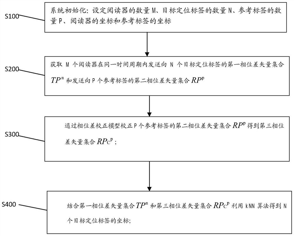
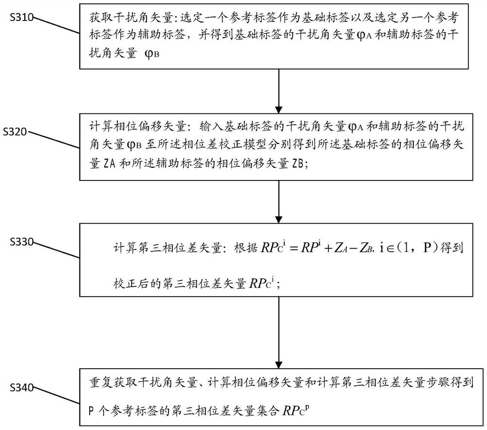
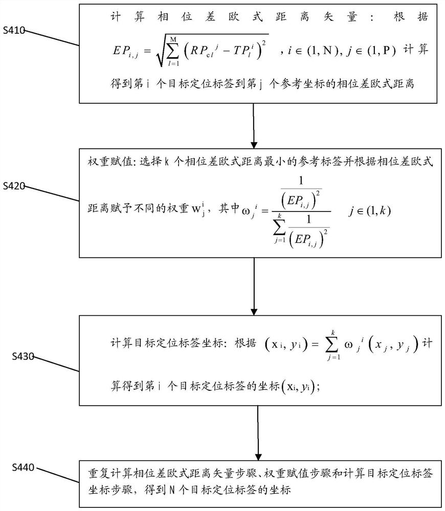
The invention discloses a phase difference correction-based RFID positioning method and device. A phase difference vector of an RFID tag is corrected through a phase difference correction model established according to a gap and an interference angle between the RFID tags, the influences of phase interference between different RFID tags are reduced, the kNN positioning algorithm accuracy is improved, and positioning of the RFID tag is more accurate.

Description

technical field [0001] The invention relates to the technical field of data processing, in particular to an RFID positioning method and device based on phase difference correction. Background technique [0002] RFID (Radio Frequency Identification) technology, that is, radio frequency identification technology. RFID radio frequency identification is a non-contact automatic identification technology, which automatically identifies target objects and obtains relevant data through radio frequency signals. RFID technology can identify high-speed moving objects and can identify multiple tags at the same time. It has the characteristics of high reading rate and fast and convenient operation; it is widely used in various fields such as logistics warehousing, asset management and personnel management. [0003] In RFID technology, a sine wave is used as the carrier signal, and the phase difference of the signal can reflect the time delay of the signal in the entire transmission proc...

Claims


Application Information

Patent Timeline
Patent Type & Authority Patents(China)
IPC IPC(8): G01S5/02G06K17/00
CPCG01S5/02G06K17/0022
Inventor 谭洪舟陈熙衡曾衍瀚王嘉奇方魏
Owner FOSHAN SHUNDE SUN YAT SEN UNIV RES INST
Learn More