Three-dimensional object pose parameter estimation method and visual equipment

A technology of three-dimensional objects and pose parameters, applied in computing, image data processing, instruments, etc., can solve the problems of difficult two-dimensional and three-dimensional straight line feature matching, tediousness, and affecting the integrity of straight line features, so as to achieve the effect of removing the influence of external points Effect

Active Publication Date: 2019-08-09
BEIHANG UNIV
View PDF12 Cites 9 Cited by
  • Summary
  • Abstract
  • Description
  • Claims
  • Application Information

AI Technical Summary

Problems solved by technology

The core problem of using straight line features for pose estimation is the matching of 2D and 3D straight line features. Since there is too little description information available for 3D straight lines, it is difficult to directly complete the matching of 2D and 3D straight line features.
One is that the reference frames that need to mark the corresponding relationship between 2D and 3D offline are large and cumbersome; the other is that the linear features of the image need to be accurately extracted, but noise, blur and other factors will affect the integrity of the linear features
[0005] From the above analysis, it can be seen that the indirect matching method realizes the pose estimation of texture-sparse objects, and relies on historical images to label reference frames, and the workload of offline labeling is large.

Method used


Image

  • Three-dimensional object pose parameter estimation method and visual equipment
  • Three-dimensional object pose parameter estimation method and visual equipment
  • Three-dimensional object pose parameter estimation method and visual equipment

Examples


Embodiment Construction

[0038] It should be understood that the specific embodiments described here are only used to explain the present invention, not to limit the present invention.

[0039] In the following description, use of suffixes such as 'module', 'part' or 'unit' for denoting elements is only for facilitating description of the present invention and has no specific meaning by itself. Therefore, 'module', 'part' or 'unit' may be used in combination.

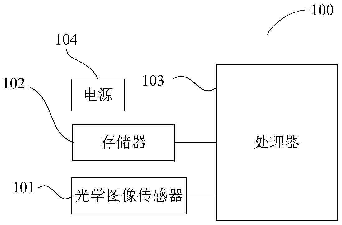
[0040] The vision devices provided in the embodiments of the present invention include but are not limited to industrial automation equipment, intelligent robots and other equipment or user terminals, which can identify and capture target objects, provide real-time image information and real-time spatial pose information of target objects. The visual device provided in the embodiment of the present invention may include: an RF (Radio Frequency, radio frequency) unit, a WiFi module, an audio output unit, an A / V (audio / video) input unit, a sensor...


PUM


Abstract

The invention relates to a three-dimensional object pose parameter estimation method and visual equipment, and the visual equipment can execute the method, and the method comprises the steps: obtaining a pose parameter determined based on a previous frame of image of a three-dimensional object, and taking the pose parameter as an initial pose parameter for determining a pose parameter corresponding to a current frame of image; projecting the three-dimensional space straight line segment of the three-dimensional object to a two-dimensional image plane based on the initial pose parameter to obtain a projection straight line segment of the three-dimensional space straight line segment on the two-dimensional image plane; determining an image straight line segment closest to the projection straight line segment on the two-dimensional image plane, and determining a distance error between the projection straight line segment and the closest image straight line segment; judging whether the distance error meets a preset condition or not; if not, determining a new pose parameter based on the distance error, and taking the new pose parameter as an initial pose parameter; and if yes, taking the initial pose parameter as the pose parameter of the current frame of image. According to the invention, the pose parameter estimation of the object with less texture is realized.

Description

technical field [0001] The present application relates to the field of visual equipment, in particular to a method for estimating pose parameters of a three-dimensional object and a visual equipment. Background technique [0002] For the pose estimation of 3D objects with sparse textures, sparse point features affect the accuracy of pose estimation, and relatively stable straight line features are beneficial to pose estimation. The core problem of using straight line features for pose estimation is the matching of 2D and 3D straight line features. Since there is too little description information available for 3D straight lines, it is difficult to directly complete the matching of 2D and 3D straight line features. Generally, the reference frame of the known two-dimensional and three-dimensional straight line correspondence is used to simplify the feature matching of two-dimensional and two-dimensional image straight lines. [0003] At present, line feature matching mainly f...

Claims


Application Information

Patent Timeline
IPC IPC(8): G06T7/73
CPCG06T2207/10012G06T7/73
Inventor 魏振忠黄周弟张广军
Owner BEIHANG UNIV
Why Eureka
Try Eureka