Rainwater cooling device for on-pole transformer

A technology of a cooling device and a transformer, which is applied in the field of transformer cooling, can solve problems such as unsuitable pole-mounted transformers, and achieve the effects of low cost, reduced heating, and good cooling effect.

Inactive Publication Date: 2019-08-09
国网河南省电力公司西峡县供电公司
View PDF5 Cites 2 Cited by
  • Summary
  • Abstract
  • Description
  • Claims
  • Application Information

AI Technical Summary

Problems solved by technology

But these are suitable for use in substations, and need to install water supply pipes, not suitable for transformers on poles

Method used


Image

  • Rainwater cooling device for on-pole transformer
  • Rainwater cooling device for on-pole transformer

Examples


Embodiment 1

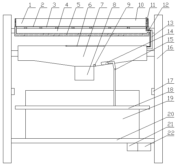
[0027] Embodiment 1. This embodiment provides a pole-mounted transformer rainwater cooling device, including a utility pole 16 and a platform main body 20 arranged on the utility pole 16. A transformer 19 is arranged on the platform main body 20. The utility pole 16 is A water collecting mechanism is arranged above the transformer 19, a water storage mechanism is arranged below the water collecting mechanism, a spray cooling mechanism connected to it is arranged below the water storage mechanism, a filtering mechanism is arranged above the water collecting mechanism, and the A control mechanism 21 connected to the water storage mechanism is arranged under the platform body 20 , and the control mechanism 21 is connected to the control center through a communication mechanism 22 .

[0028] The water collection mechanism includes a water collection plate 5 provided on the utility pole 16, the upper surface of the water collection plate 5 is provided with a water collection pit 4, ...

Embodiment 2

[0031] The difference between this embodiment and Embodiment 1 is:

[0032] The water storage mechanism includes a water storage tank 7 arranged below the water collecting plate 5, the water storage tank 7 is a rectangular structure, the inside of the water storage tank 7 communicates with the first pipeline 13, and the first A pressure regulating pipe 11 is arranged in the pipeline 13 , the lower end of the pressure regulating pipe 11 communicates with the inside of the water storage tank 7 , and the height of the upper end of the pressure regulating pipe 11 is greater than the height of the water collecting plate 5 . The water storage tank can be set in a flat structure, but the water storage tank has no other mechanism to communicate with the outside except the first pipe, so a pressure regulating pipe needs to be installed, otherwise the water enters from the first pipe, and the internal gas cannot be discharged, and it will As a result, the internal air pressure is relati...

Embodiment 3

[0036] The difference between this embodiment and Embodiment 1 is:

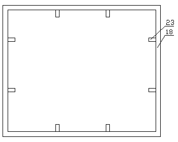
[0037] The spray cooling mechanism includes a ring of pressure pipes 18 arranged around the transformer 19, the inner side of the pressure pipe 18 is provided with an atomizing nozzle 23 communicating with the pressure pipe 18, and the pressure pipe 18 is connected to the pressurized water pump through the second pipe 15 14 connected. The pressurized water pump pressurizes the water into the pressure pipe, and the water is sprayed from the atomizing nozzle through the pressure to spray and cool the surface of the transformer. The atomized spray is used to make the watering more uniform and save water.

[0038] The filter mechanism includes a support frame 3 provided on the water collection plate 5 at the upper end of the water collection pit 4, a filter screen 2 is arranged on the support frame 3, and a water retaining plate 5 extends upwards along the edge of the water collection plate 5. plate 1. The filt...


PUM


Abstract

The invention provides a rainwater cooling device for an on-pole transformer. The device comprises a telegraph pole and a platform main body arranged on the telegraph pole, the platform main body is provided with a transformer, the telegraph pole is provided with a water collection mechanism arranged at the upper portion of the transformer, the lower portion of the water collection mechanism is provided with a water storage mechanism, the lower portion of the water storage mechanism is provide with a spraying cooling mechanism communicating with the water storage mechanism, the upper portion of the water collection mechanism is provided with a filtering mechanism, the lower portion of the platform main body is provided with a control mechanism in signal connection with the water storage mechanism, and the control mechanism is connected with a control center through a communication mechanism. The rainwater cooling device for the on-pole transformer can effectively reduce the temperatureof the on-pole transformer and can ensure the normal operation of the transformer.

Description

technical field [0001] The invention relates to the technical field of transformer cooling, in particular to a pole-mounted transformer rainwater cooling device. Background technique [0002] The heat dissipation and cooling of power transformers during operation plays an important role in the safe operation of transformers. Common power transformers are mainly oil-immersed transformers, and the main heat dissipation components are radiators composed of multiple groups of fins connected by sheet-like heat sinks, which use air convection to naturally cool down and install fans at the bottom of the heat sinks. Cool down the heat sink by blowing air to speed up the air circulation, which can meet the operation requirements of the transformer under normal circumstances; In the case of load operation, the oil temperature in the transformer is high, and the original heat dissipation method cannot meet the requirements. In order to ensure the safe operation of the transformer, the...

Claims


Application Information

Patent Timeline
IPC IPC(8): H01F27/16
CPCH01F27/16
Inventor 赵晨薛顾一张硕杜永玺王嘉伟李尧
Owner 国网河南省电力公司西峡县供电公司
Why Eureka
Try Eureka