Electrified railway in-phase traction power supply system and control method thereof

A traction power supply system, electrified railway technology, applied in the direction of reducing/preventing power oscillation, AC network load balancing, single-network parallel feeding arrangement, etc. , traction network and on-board equipment burning and other problems, to achieve the effect of improving flexibility, easy to compensate for capacity expansion, and superior performance

Pending Publication Date: 2019-08-09
CHENGDU SHANGHUA ELECTRIC CO LTD
View PDF0 Cites 9 Cited by
  • Summary
  • Abstract
  • Description
  • Claims
  • Application Information

AI Technical Summary

Problems solved by technology

In order to prevent electric locomotives from burning catenary suspension components due to electric split phases due to electric phase separation, and even causing phase-to-phase short circuits and other accidents, as the train speed continues to increase, when the driver cannot manually degrade, turn off auxiliary units, and disconnect the main When the circuit breaker is driven through the neutral section by the inertia of the train, the main circuit breaker is closed again, the auxiliary unit is closed, and the traction power is upgraded to restore the traction power to complete the phase separation, the automatic phase separation technology is adopted, mainly the ground switch automatically switches the phase separation , on-board automatic over-phase separation and on-column automatic over-phase equalization, but there is still a transient electrical process in which the train passes through the electric phase separation during switch switching, which is easy to generate large operating overvoltage or overcurrent, causing the traction network and on-board equipment to burn. damage and other accidents, affecting the reliability of power supply and the safe operation of trains

Method used


Image

  • Electrified railway in-phase traction power supply system and control method thereof
  • Electrified railway in-phase traction power supply system and control method thereof
  • Electrified railway in-phase traction power supply system and control method thereof

Examples


Embodiment 1

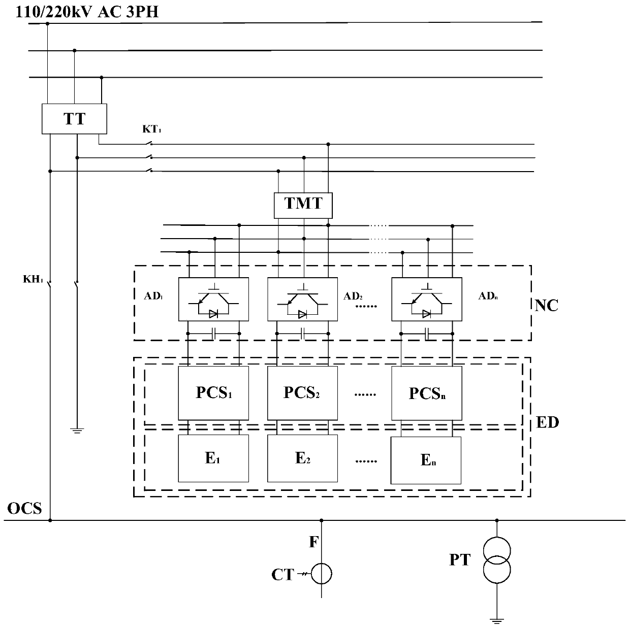
[0047] like figure 1 As shown, the embodiment of the present invention provides an electrified railway in-phase traction power supply system, wherein the in-phase traction power supply system includes a traction transformer TT for transforming the line voltage of the three-phase high-voltage bus to the traction bus OCS, for The compensation matching transformer TMT for the energy conversion of the traction transformer TT, the in-phase compensation device NC for power quality compensation of the in-phase traction power supply system, the energy storage device ED for storing electric energy and controlling charging and discharging, and for detecting the Active power positive and negative, magnitude of voltage and current, coordination of real-time charge and discharge of energy storage device ED and measurement and control device MC of power quality compensation of non-phase compensation device NC. The primary side of the traction transformer TT is connected to the three-phase h...

Embodiment 2

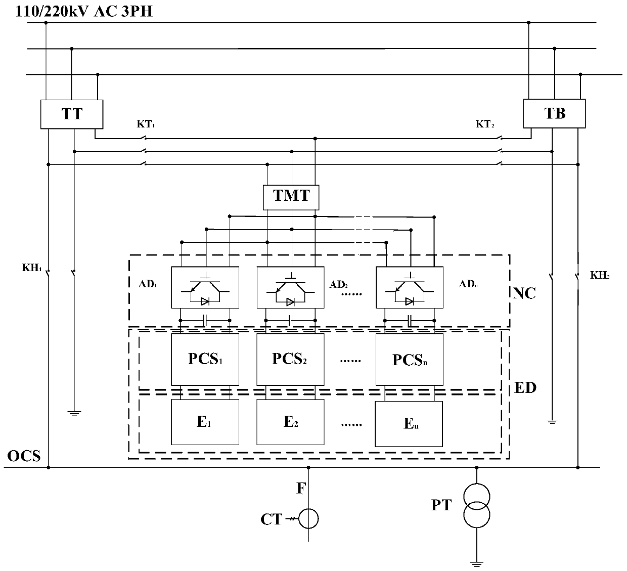
[0054] like image 3 As shown, the embodiment of the present invention provides an electrified railway in-phase traction power supply system. The main difference from the embodiment of the present invention is that the in-phase traction power supply system also includes a device for converting the line voltage of the three-phase high-voltage bus to the traction bus. A standby traction transformer TB, the primary side of the standby traction transformer TB is connected to the three-phase high-voltage bus, and any two terminals of the secondary side are connected to the traction load; the secondary side of the standby traction transformer TB passes through the second circuit breaker KT 2 It is connected with the primary side of the compensation matching transformer TMT. Other technical features are completely the same as those in Embodiment 1 of the present invention, and will not be repeated here.

[0055] Generally, under normal conditions, the traction transformer TT, the co...

Embodiment 3

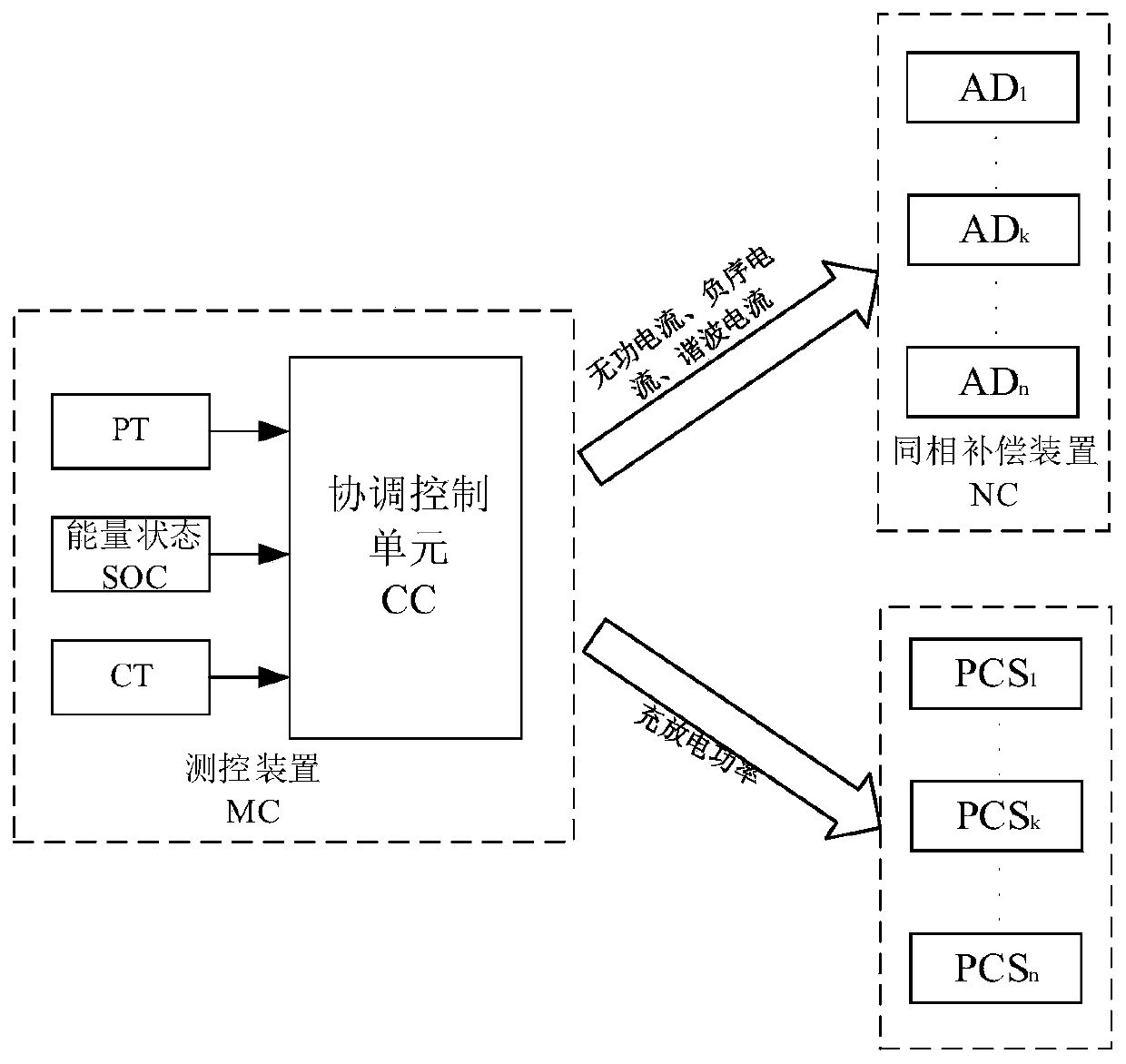
[0057] like Figure 4 and Figure 5 As shown, the embodiment of the present invention provides a control method of the same-phase traction power supply system for electrified railways, wherein the specific steps of the control method include charging and discharging of the energy storage device ED and power quality compensation of the same-phase compensation device NC, wherein, The specific steps of the control method of the power quality compensation of the in-phase compensation device NC are:


PUM


Abstract

The invention discloses an electrified railway in-phase traction power supply system and a control method thereof. The in-phase traction power supply system comprises a traction transformer, a compensation matching transformer, an in-phase compensation device, an energy storage device and a measurement and control device. The primary side of the traction transformer is connected with a three-phasehigh-voltage bus, and any two terminals of the secondary side are connected with a traction load. The primary side of the compensation matching transformer is connected with the secondary side of thetraction transformer. The alternating current end of the in-phase compensation device is connected with the secondary side of the compensation matching transformer. The energy storage device is connected with the direct current end of the in-phase compensation device. The measurement and control device is connected with the in-phase compensation device and the energy storage device. According tothe invention, cophase supply of the whole railway is realized, and electric phase separation is cancelled; technical and economic optimization of cophase supply of an electrified railway is effectively realized; and the power quality problem of the negative sequence of a three-phase system, which is caused by the electric locomotive load of the electrified railway, is solved.

Description

technical field [0001] The invention relates to the field of AC electrified railway power supply, in particular to an electrified railway in-phase traction power supply system and a control method thereof. Background technique [0002] The electrified railway in my country generally adopts single-phase power frequency AC system. In order to make the single-phase traction load as balanced as possible in the three-phase power system, the electrified railway often adopts the scheme of alternating phase sequence and split-phase partition power supply. The adjacent power supply intervals at the phase separation partition form a phase separation insulator, which is called electrical phase separation or phase separation. In order to prevent electric locomotives from burning catenary suspension components due to electric split phases due to electric phase separation, and even causing phase-to-phase short circuits and other accidents, as the train speed continues to increase, when th...

Claims


Application Information

Patent Timeline
Patent Type & Authority Applications(China)
IPC IPC(8): H02J3/24H02J3/48H02J3/32
CPCH02J3/24H02J3/32H02J3/48
Inventor 吴波杨智灵张伟鹏
Owner CHENGDU SHANGHUA ELECTRIC CO LTD
Why Eureka
Try Eureka