High performance voltage controllable electrical power supply

A power supply, high-performance technology, applied in current collectors, battery circuit devices, electric vehicles, etc., to achieve the effect of ensuring normal use

Inactive Publication Date: 2019-08-09
YUEXI SWAN ELECTRONICS TECH
View PDF0 Cites 2 Cited by
  • Summary
  • Abstract
  • Description
  • Claims
  • Application Information

AI Technical Summary

Problems solved by technology

[0003] The purpose of the present invention is to provide a high-performance voltage-controllable electrical power supply to solve the problem of how to quickly and controllably adjust the connected voltage before the electrical equipment is connected in the above-mentioned background technology

Method used


Image

  • High performance voltage controllable electrical power supply
  • High performance voltage controllable electrical power supply
  • High performance voltage controllable electrical power supply

Examples


Embodiment 1

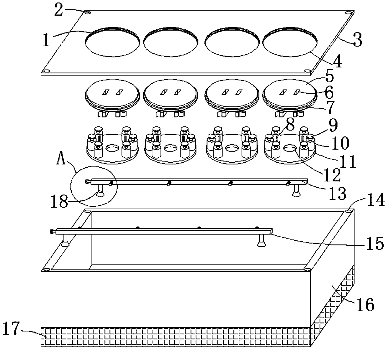
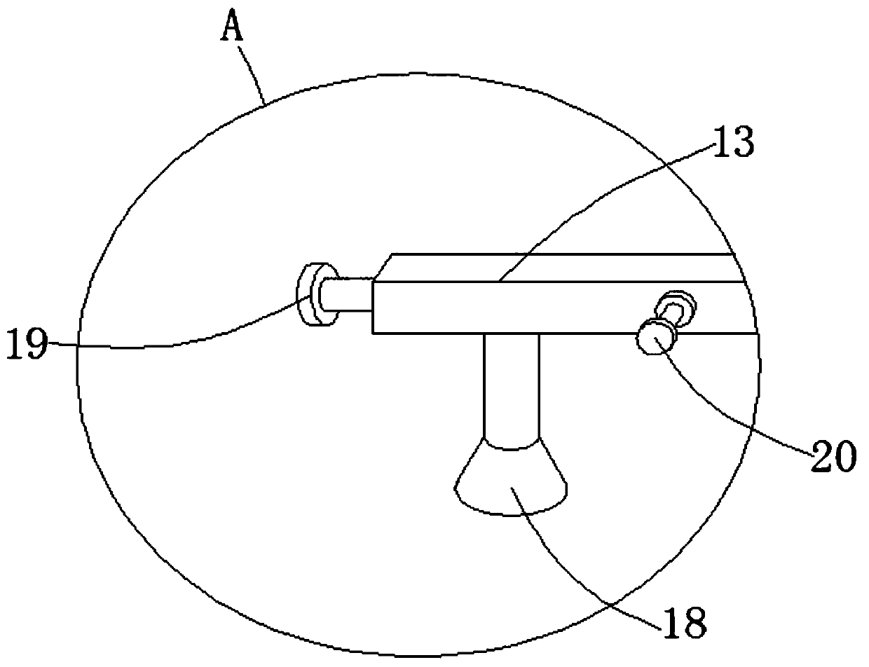
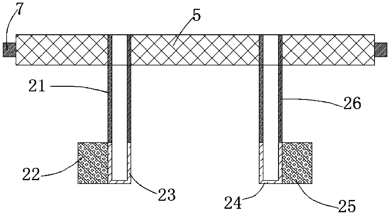
[0020] see Figure 1-3 , this embodiment provides a high-performance voltage-controllable electrical power supply, including a housing 16, an upper cover 3, several sockets 5 and several insulating mounting plates 11, the inner cavity of the housing 16 is a hollow structure, The upper cover 3 is located directly above the shell 16 and is matched with each other. The upper cover 3 is provided with several circular openings 4, and the inner chamber side walls of the several circular openings 4 are all provided with annular chute 1, and several plug-in The outer wall of the seat 5 is extended with an annular slider 7, and each socket 5 is rotated and clamped with the annular chute 1 of each circular port 4 through the annular slider 7, and each socket 5 is provided with Two left and right symmetrical insertion holes 6, each socket 5 is fixedly connected with the live wire insulating plastic sleeve 21 and the neutral wire insulating plastic sleeve 26 through the two insertion hole...

Embodiment 2

[0023] see Figure 1-3 , on the basis of Embodiment 1, a further improvement has been made: the top faces of several receptacles 5 are flush with the top faces of the upper cover 3, so that the plugs of electrical appliances are inserted into the inner cavity of the socket hole 6, and the live wire insulating plastic The top surfaces of the cover 21 and the neutral line insulating plastic cover 26 are flush with the top surface of the receptacle 5, and the purpose of such setting is also to make the plug of the electrical appliance fully inserted into the inner cavity of the live line insulating plastic cover 21 and the neutral line insulating plastic cover 26. , the live wire conductive sleeve 23 and the neutral wire conductive sleeve 24 are made of copper, the thickness of the first arc-shaped pick 22 and the second arc-shaped pick 25 are both 1 mm, and the thickness of the first arc-shaped pick 22 and the second arc pick 25 are 1 mm. Two arc-shaped paddles 25 can not only p...


PUM


Abstract

The invention discloses a high performance voltage controllable electrical power supply comprising a housing, an upper cover, multiple plugging sockets and multiple insulating installing discs. Each plugging socket is rotatably clamped with each annular slide slot with a circular opening by an annular slide block. Each plugging socket is provided with two left-and-right symmetrical plugging jacks.A fire wire insulating plastic sleeve and a zero wire insulating plastic sleeve are fixedly plugged into each plugging socket through two plugging jacks. A fire wire conductive sleeve and a zero wireconductive sleeve are connected on the bottom end surfaces of the fire wire insulating plastic sleeve and the zero wire insulating plastic sleeve. Multiple resistors are vertically arranged on the top end surfaces of multiple insulating installing discs. A first conductive copper sheet and a second conductive copper sheet are horizontally arranged on the front and rear sides of the bottom end surface of the inner cavity of the housing through an insulating plastic support rod respectively. Normal use of the electrical power supplies of different power can be protected from being overloaded orunder-voltage to the circuit by changing the input voltage of the electrical appliance.

Description

technical field [0001] The invention relates to the related technical field of electric power supply for equipment, in particular to a high-performance voltage controllable electric power supply. Background technique [0002] We know that if any electrical appliance is to operate normally, it needs to provide a unit power supply to meet the use of electrical appliances. At present, there is no electrical power supply in the market that can adjust the output voltage to meet the use of electrical equipment with different rated power. , In many cases, it is necessary to connect an external transformer to achieve the purpose of stepping down or boosting the voltage, in case of overvoltage or undervoltage when the appliance is in use, whether it is overvoltage or undervoltage, the normal operation of the appliance will be affected. Therefore, how to quickly and controllably adjust the connected voltage before the device is connected needs to be solved urgently. Therefore, a high-...

Claims


Application Information

Patent Timeline
Patent Type & Authority Applications(China)
IPC IPC(8): H02J7/00H01R13/11H01R13/02
CPCH01R13/02H01R13/11H02J7/0042H02J7/0063
Inventor 储荣生
Owner YUEXI SWAN ELECTRONICS TECH
Why Eureka
Try Eureka