
Magnetorheological fluid-based electric power anti-misplug socket

A magnetorheological fluid, anti-unplug technology, applied in circuits, electrical components, parts of connecting devices, etc., can solve problems such as delaying work progress, stopping power equipment, damage to power equipment parts, etc., to increase the connection strength. , Guarantee the sensitivity, prevent the effect of mistakenly pulling out

Inactive Publication Date: 2021-02-05
李英艳
View PDF7 Cites 0 Cited by
  • Summary
  • Abstract
  • Description
  • Claims
  • Application Information

AI Technical Summary

Problems solved by technology

[0002] According to incomplete statistics, there are more than 1,500 domestic companies producing switch and socket products, and the quality of the products varies greatly. Because many ordinary consumers do not have the method to identify the pros and cons of products, and the knowledge of switch and socket brands is limited, It brings living space to some unscrupulous businessmen, and some counterfeit and inferior products flow into the market. There are many types of power sockets at present, but there are still a lot of problems in use, and the most serious problem is that the plug is easy to be pulled out by mistake.
[0003] When the current socket is in use, because the plug and the socket are inserted, the connection between the plug and the socket is not tight enough, causing the plug to fall off easily under the action of external force, causing the power equipment to stop working, delaying the work progress, and Sudden power failure is very likely to cause damage to the internal parts of the power equipment, which greatly reduces the practicability of the plug.

Method used


Image

  • Magnetorheological fluid-based electric power anti-misplug socket
  • Magnetorheological fluid-based electric power anti-misplug socket
  • Magnetorheological fluid-based electric power anti-misplug socket

Examples


Embodiment Construction

[0019] The following will clearly and completely describe the technical solutions in the embodiments of the present invention with reference to the accompanying drawings in the embodiments of the present invention. Obviously, the described embodiments are only some, not all, embodiments of the present invention. Based on the embodiments of the present invention, all other embodiments obtained by persons of ordinary skill in the art without making creative efforts belong to the protection scope of the present invention.

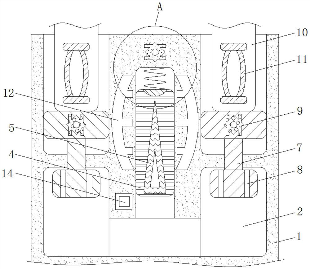
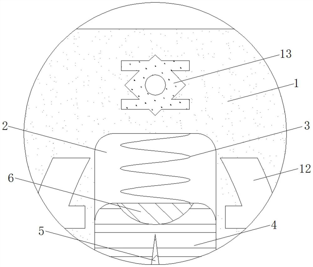
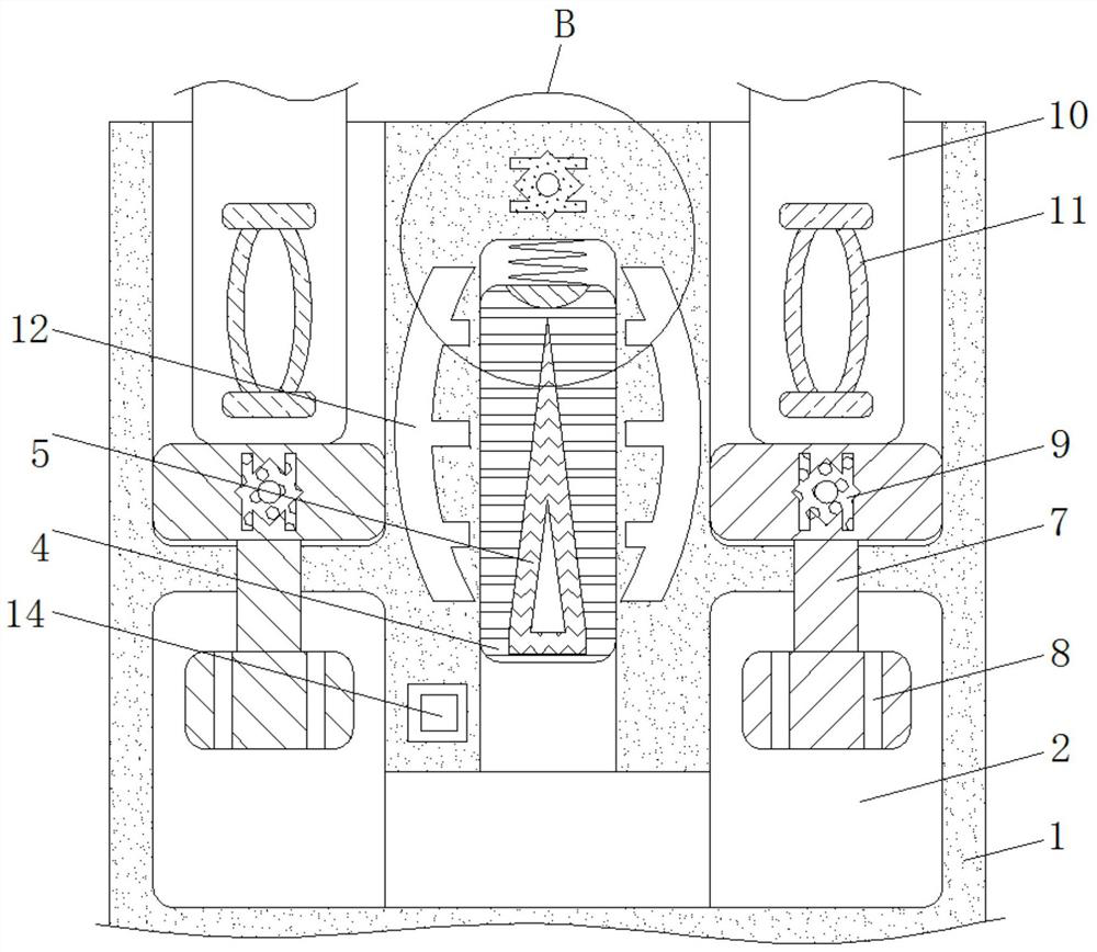
[0020] see Figure 1-4 , a magneto-rheological fluid-based anti-mis-unplug socket for electric power, including a socket 1, the material of the socket 1 is a hard high-strength material and the socket 1 does not have electrical conductivity and magnetic conductivity, and the socket 1 plays the role of fixing various components , the interior of the hydraulic tank 2 is filled with magnetorheological fluid and the shape of the hydraulic tank 2 is a "mountain" sh...


PUM


Abstract

The invention relates to the technical field of electric power, in particular to a magnetorheological fluid-based electric power anti-misplug socket which comprises a socket, a hydraulic groove is formed in the bottom of the socket, a spring is fixedly connected to the top of the middle of the hydraulic groove, and a piston block is fixedly connected to the bottom of the spring. A dielectric plateis fixedly connected to the middle of the piston block, a first iron block is fixedly connected to the top of the piston block, sliding blocks are movably connected to the two sides of the hydraulicgroove, and damping holes which are evenly distributed are formed in the bottoms of the sliding blocks. According to the magnetorheological fluid-based electric power anti-misplug socket, through thecooperative use of an electromagnet I and an iron block II, when a plug is completely inserted into the socket, the magnetism of the electromagnet is increased to the maximum extent, so that an iron block I and an electromagnet I attract each other, the connection strength between the plug and the socket is improved, the effect of preventing the plug from being pulled out by mistake is effectivelyachieved, and the working stability of power equipment is improved.

Description

technical field [0001] The invention relates to the technical field of electric power, in particular to a magneto-rheological fluid-based anti-mis-unplug socket for electric power. Background technique [0002] According to incomplete statistics, there are more than 1,500 domestic companies producing switch and socket products, and the quality of the products varies greatly. Because many ordinary consumers do not have the method to identify the pros and cons of products, and the knowledge of switch and socket brands is limited, It brings living space to some unscrupulous businessmen, and some counterfeit and shoddy products flow into the market. There are many types of power sockets at present, but there are still a lot of problems in use, and the most serious problem is that the plug is easy to be pulled out by mistake. [0003] When the current socket is in use, because the plug and the socket are inserted, the connection between the plug and the socket is not tight enough...

Claims


Application Information

Patent Timeline
IPC IPC(8): H01R13/639H01R13/66
CPCH01R13/639H01R13/6616H01R13/665
Inventor 李英艳
Owner 李英艳
Learn More