
Brake system with two pressure sources and two methods of brake system operation

A brake system and pressure technology, which is applied in the direction of brake control system, ABS control system, brake action activation device, etc., can solve the problem of wheel brake pressure dissipation and achieve the effect of reducing costs

Active Publication Date: 2021-08-27
CONTINENTAL AUTOMOTIVE TECH GMBH
View PDF8 Cites 0 Cited by
  • Summary
  • Abstract
  • Description
  • Claims
  • Application Information

AI Technical Summary

Problems solved by technology

In the opposite case, the movement of the linear actuator back in the direction of its rest position causes the pressure in the wheel brake to dissipate

Method used


Image

  • Brake system with two pressure sources and two methods of brake system operation
  • Brake system with two pressure sources and two methods of brake system operation
  • Brake system with two pressure sources and two methods of brake system operation

Examples


Embodiment Construction

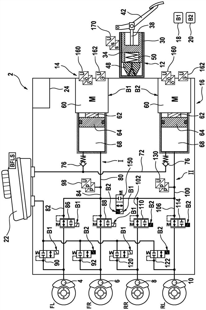
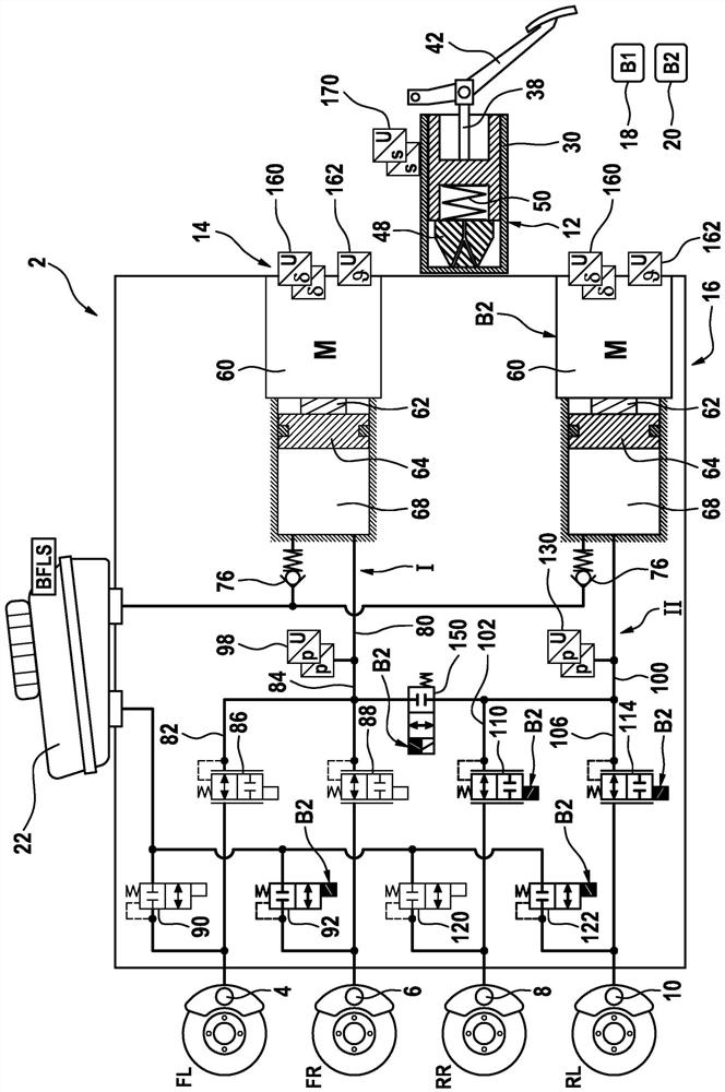
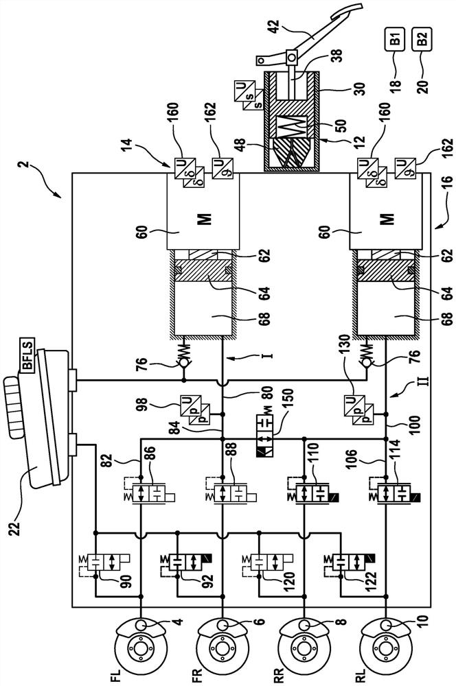
[0037] figure 1 The braking system 2 shown in includes: four hydraulically actuatable wheel brakes 4, 6, 8, 10, a simulator 12, two pressure supply devices 14, 16, two independent on-board electrical systems 18, 20 , a pressure medium reservoir 22 at atmospheric pressure, and an open-loop and closed-loop control unit 24 .

[0038] Simulator 12 in the form of a master brake cylinder comprises a master brake cylinder piston 34 which is arranged in master brake cylinder housing 30 and which is coupled to a brake pedal 42 by means of a piston rod 38 . In the event of actuation of the brake pedal 42 , the brake master cylinder piston 34 presses against a spring element 48 which is likewise arranged in the brake master cylinder housing 30 . Another elastic element 50 supports the piston 34 on the elastic element 48 and pushes the piston 34 into its rest position when the brake pedal is not actuated. The simulator 12 is of dry design, that is to say it does not comprise a pressure ...


PUM


Abstract

A braking system (2) is disclosed comprising four hydraulically actuatable wheel brakes (4, 6, 8, 10), wherein each wheel brake (4, 6, 8, 10) is Each case is assigned a de-energized closed outlet valve (90, 92, 120, 122), wherein each wheel brake (4, 6, 8, 10) is respectively assigned a de-energized open inlet valves (86, 88, 110, 114), the brake system also includes a simulator (12) actuatable by the brake pedal (42), wherein two pressure supply devices (14, 16) are provided For the active build-up of pressure in these wheel brakes (4, 6, 8, 10), two brake circuits (I, II) are formed hydraulically, wherein in each brake circuit (I, II), in each case one pressure supply device (14, 16) is hydraulically connected to the two wheel brakes (4, 6, 8, 10), and wherein two separate on-board electrical systems (18 , 20), and wherein each pressure providing device (14, 16) is powered by one of the two on-board electrical systems (18, 20) in each case.

Description

technical field [0001] The invention relates to a braking system comprising four hydraulically actuatable wheel brakes, wherein each wheel brake is assigned in each case a de-energized outlet valve, wherein each wheel brake Assigned in each case with an inlet valve that opens when de-energized, the brake system includes a simulator actuatable via the brake pedal, in which two pressure supply devices are provided for active build-up in the wheel brakes pressure. The invention also relates to a corresponding operating method. Background technique [0002] In motor vehicle engineering, "brake-by-wire" brake assemblies are becoming more widely used. Such brake assemblies usually have not only a master brake cylinder that can be actuated by the vehicle driver, but also an electrically activatable pressure supply ("wire-by-wire" activatable), by means of which brake assemblies can be The "brake-by-wire" operating mode implements the actuation of the wheel brakes. [0003] In t...

Claims


Application Information

Patent Timeline
Patent Type & Authority Patents(China)
IPC IPC(8): B60T8/32
CPCB60T8/326B60T2270/413B60T8/3645B60T8/4081B60Y2400/81B60T7/042B60T8/4086B60T13/161B60T13/168B60T13/686B60T2270/10B60T2270/402B60T2270/403B60T2270/82
Inventor B·马吉H·科尔曼T·米利克A·肖恩博姆R·施罗德M·伦茨M·布莱茨J·施密特D·丁克尔
Owner CONTINENTAL AUTOMOTIVE TECH GMBH
Learn More