
Base plate fixing device of heater rod bending forming machine

A technology for fixing devices and molding machines, applied in positioning devices, feeding devices, storage devices, etc., can solve problems such as fixing troubles, loose bolts, inconvenient replacement of molding machines, etc., to prevent loosening, increase friction, and facilitate replacement Effect

Pending Publication Date: 2019-08-13
ANHUI NINGGUO TIANCHENG ELECTRICAL APPLIANCES
View PDF0 Cites 4 Cited by
  • Summary
  • Abstract
  • Description
  • Claims
  • Application Information

AI Technical Summary

Problems solved by technology

[0003] The purpose of the present invention is to provide a bottom plate fixing device for a heater rod bending machine to solve the problem that the existing processing table proposed in the background technology is very troublesome to fix, and after a long time of use, it is easy to appear fixed The bolts are loose, and the existing processing table is also prone to vibration, and it is inconvenient to replace the molding machine

Method used


Image

  • Base plate fixing device of heater rod bending forming machine
  • Base plate fixing device of heater rod bending forming machine
  • Base plate fixing device of heater rod bending forming machine

Examples


Embodiment 1

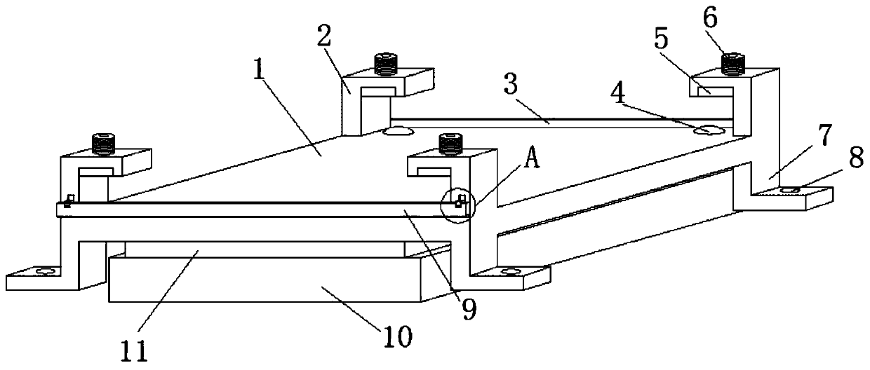
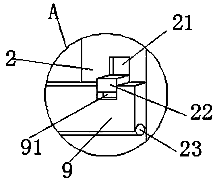
[0026] see figure 1 , Figure 6 , Figure 7 and Figure 8 , this embodiment provides a bottom plate fixing device for a heater rod bending machine, including a base 1, a press frame 2 is fixedly installed on the four corners of the upper end surface of the base 1, and the groove on the inner top of the press frame 2 A briquetting block 5 is installed in the briquetting block 5, and a threaded rod 6 is fixedly installed on the top of the briquetting rod 6. The top of the threaded rod 6 is provided with an inner hexagonal hole, which can regulate the threaded rod 6. The threaded rod 6 runs through the pressure On the top of the frame 2, one end of the base 1 is fixedly equipped with a first baffle 3, and both sides of the first baffle 3 are fixed on the outside of the press frame 2, and the other side of the base 1 is rotatably installed with The second baffle plate 9, the four corners of the lower end of the base 1 are fixedly installed with a mounting frame 7, and the lower...

Embodiment 2

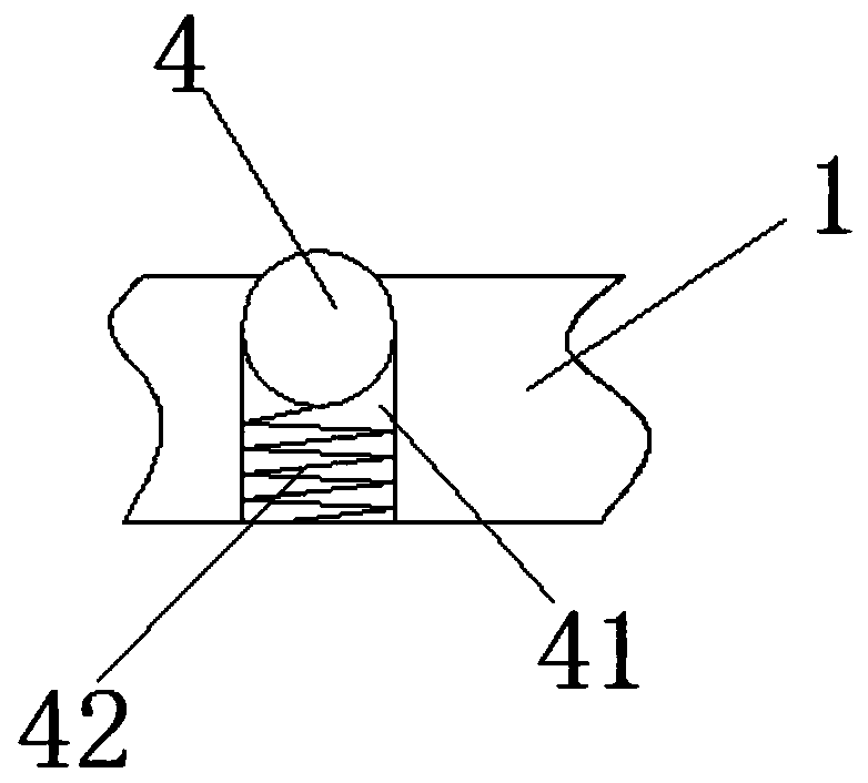
[0030] see Figure 2-5 , made a further improvement on the basis of Example 1: the top ball 4 is installed on the slide of the base 1, the top ball 4 is located on the upper end surface of the base 1 inside the press frame 2, and the upper end surface of the base 1 is provided with A placement groove 41 matched with the top ball 4, the bottom of the placement groove 41 is fixedly equipped with a first spring 42, and the top of the first spring 42 is fixedly welded with the top ball 4, by setting the top ball 4 and the first spring 42. When the base 1 fixes the bottom plate of the molding machine, while the threaded rod 6 and the pressure block 5 exert pressure on the bottom plate of the molding machine, the bottom plate of the molding machine also has pressure on the top ball 4, and the top ball is under the pressure of the first spring 42 Under the action, there will be an upward elastic force on the bottom plate of the molding machine, and the elastic force of the spring wil...


PUM


Abstract

The invention discloses a base plate fixing device of a heater rod bending forming machine. The device comprises a base; pressing frames are fixedly mounted at four angles of the upper end surface ofthe base; pressing blocks are mounted in grooves at the tops of the inner sides of the pressing frames; thread rods are fixedly mounted at the tops of the pressing blocks; the thread rods penetrate through the tops of the pressing frames; a first baffle plate is fixedly mounted at one end of the base; two sides of the first baffle plate are fixed on the outer sides of the pressing frames; a secondbaffle plate is rotationally mounted on the other side of the base; mounting frames are fixedly mounted at four angles of the lower end of the base; support plates are fixedly mounted on the lower end surface of the base on the inner sides of the mounting frames; and slide plates capable of vertically sliding are slidingly mounted at the lower ends of the mounting frames. In the device, the pressing frames can achieve a pressing effect on machined base plates mounted on the base; and thread rods can be used for adjusting the heights of the pressing blocks to meet the base plates with different thicknesses and sizes, so that the problems of simpler fixed plates and capability of fixing the base plates with one thickness in the prior art are solved.

Description

technical field [0001] The invention relates to the technical field of heaters, in particular to a bottom plate fixing device of a heater rod bending forming machine. Background technique [0002] With the improvement of life, more and more heating tubes are used. When bending and forming the heating tubes, the forming frames of the heating tubes are generally fixed on the processing machine tool, or directly on the processing table, often directly Fixing with bolts is very troublesome when fixing, and it is inconvenient to replace the bottom plate of the molding machine. After a long time of use, the fixed bolts are prone to loosening, and the existing processing table is also prone to vibration. The fixed plate is relatively simple, and can only fix the bottom plate of a single thickness. Contents of the invention [0003] The purpose of the present invention is to provide a bottom plate fixing device for a heater rod bending machine to solve the problem that the existi...

Claims


Application Information

Patent Timeline
Patent Type & Authority Applications(China)
IPC IPC(8): B21D43/00B21D7/16
CPCB21D43/00B21D7/16
Inventor 汪洋
Owner ANHUI NINGGUO TIANCHENG ELECTRICAL APPLIANCES
Learn More