Eureka AIR delivers breakthrough ideas for toughest innovation challenges, trusted by R&D personnel around the world.

A steel pipe punching machine

A technology for punching machines and steel pipes, which is applied in the direction of boring/drilling, drilling/drilling equipment, metal processing machinery parts, etc., and can solve problems such as reducing the quality of processing, affecting the quality of operation, and offsetting materials to be processed. , to achieve the effect of improving the quality of

Active Publication Date: 2018-02-06
无锡市汇鼎金属制管有限公司
View PDF6 Cites 0 Cited by
  • Summary
  • Abstract
  • Description
  • Claims
  • Application Information

AI Technical Summary

Problems solved by technology

[0002] In steel pipe manufacturing and processing, punching machines are often used to punch holes for production, but most of the current punching machines do not have the ability to collect debris, and often the residual debris after drilling will affect the next time. The quality of the operation, and due to the large force of the punching, it is easy to cause the material to be processed to shift, which affects the accuracy of the punching, thereby reducing the quality of the processing

Method used

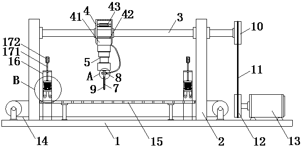

Image

  • A steel pipe punching machine
  • A steel pipe punching machine
  • A steel pipe punching machine

Examples


Embodiment Construction

[0014] The following will clearly and completely describe the technical solutions in the embodiments of the present invention with reference to the accompanying drawings in the embodiments of the present invention. Obviously, the described embodiments are only some, not all, embodiments of the present invention. Based on the embodiments of the present invention, all other embodiments obtained by persons of ordinary skill in the art without making creative efforts belong to the protection scope of the present invention.

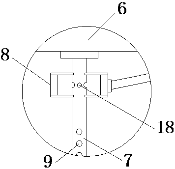
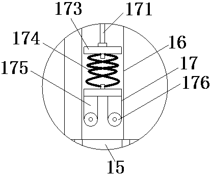
[0015] see Figure 1-3 , the present invention provides a technical solution: a steel pipe punching machine, including a base 1, a support frame 2 is fixedly installed on both ends of the upper surface of the base 1, a moving screw 3 is set on the support frame 2, and a moving screw 3 When it rotates, it will drive the chip collecting mechanism to move. The moving screw rod 3 is equipped with a chip collecting mechanism 4. The chip collecting mechanism 4 inclu...


PUM


Abstract

The invention discloses a steel pipe perforating machine which comprises a base. Supporting frames are fixedly mounted at the two ends of the upper surface of the base. A moving lead screw is mounted on the supporting frames in a sleeved manner. A scrap collection mechanism is mounted on the moving lead screw in a sleeving manner. The bottom end of the scrap collection mechanism is fixedly connected with an electric telescopic rod. The end, far away from the scrap collection mechanism, of the electric telescopic rod is fixedly connected with a perforating motor. A drill bit is fixedly mounted on an output shaft of the perforating motor. A scrap guide hole communicating with the scrap collection mechanism through a hose is formed in the top of the drill bit. A sealing piece is arranged on the outer portion of the scrap guide hole, wherein the drill bit is sleeved with the sealing piece. Scrap collection holes communicating with the scrap guide hole are formed in the bottom end of the drill bit at equal distance. One end of the moving lead screw penetrates and extends out of one supporting frame to be fixedly connected with the axis of a driven disc. According to the steel pipe perforating machine, the scrap collection holes are formed in the drill bit and cooperate with the scrap collection mechanism, negative pressure is generated through a draught fan, and therefore scraps generated by machining can be collected, and the situation that the scraps are accumulated, and consequently next machining is influenced is avoided.

Description

technical field [0001] The invention relates to the technical field of machinery manufacturing equipment, in particular to a steel pipe punching machine. Background technique [0002] In steel pipe manufacturing and processing, punching machines are often used to punch holes for production, but most of the current punching machines do not have the ability to collect debris, and often the residual debris after drilling will affect the next time. The quality of the operation, and because the punching force is relatively large when punching, it is easy to cause the material to be processed to shift, which affects the accuracy of the punching, and then reduces the quality of the processing. Contents of the invention [0003] The object of the present invention is to provide a steel pipe punching machine to solve the problems raised in the above background technology. [0004] In order to achieve the above object, the present invention provides the following technical solution...

Claims


Application Information

Patent Timeline
Patent Type & Authority Patents(China)
IPC IPC(8): B23B41/00B23B47/20B23Q11/00B23Q3/06
CPCB23B41/00B23Q3/064B23Q5/36B23Q5/40B23Q11/0046
Inventor 陈海兵
Owner 无锡市汇鼎金属制管有限公司
Why Eureka
Eureka Blog
Learn More