Light path calibration tool and method

An optical path and tool technology, applied in the field of optical path calibration tools, can solve the problems of inconvenient use, inaccurate light calibration, different aperture processing errors, etc., and achieve the effect of convenient use.

Pending Publication Date: 2022-05-06
QUANTUMCTEK
View PDF1 Cites 0 Cited by
  • Summary
  • Abstract
  • Description
  • Claims
  • Application Information

AI Technical Summary

Problems solved by technology

[0004] (1) Every time the light turns, the aperture needs to be screwed into the fixed hole that runs through the surface of the optical table to calibrate the optical path. The calibration process is relatively complicated and inconvenient to use;
[0005] (2) Due to the need to use multiple apertures for calibration at the same time, the processing error of different apertures is different, which will affect the accuracy of light calibration;
[0006] (3) The aperture bracket has a threaded structure, and the aperture bracket needs to be manually rotated and screwed into the fixing hole of the optical table. Different torques will lead to different positions of screwing into the fixing hole, resulting in inaccurate light calibration

Method used


Image

  • Light path calibration tool and method
  • Light path calibration tool and method
  • Light path calibration tool and method

Examples


Embodiment 1

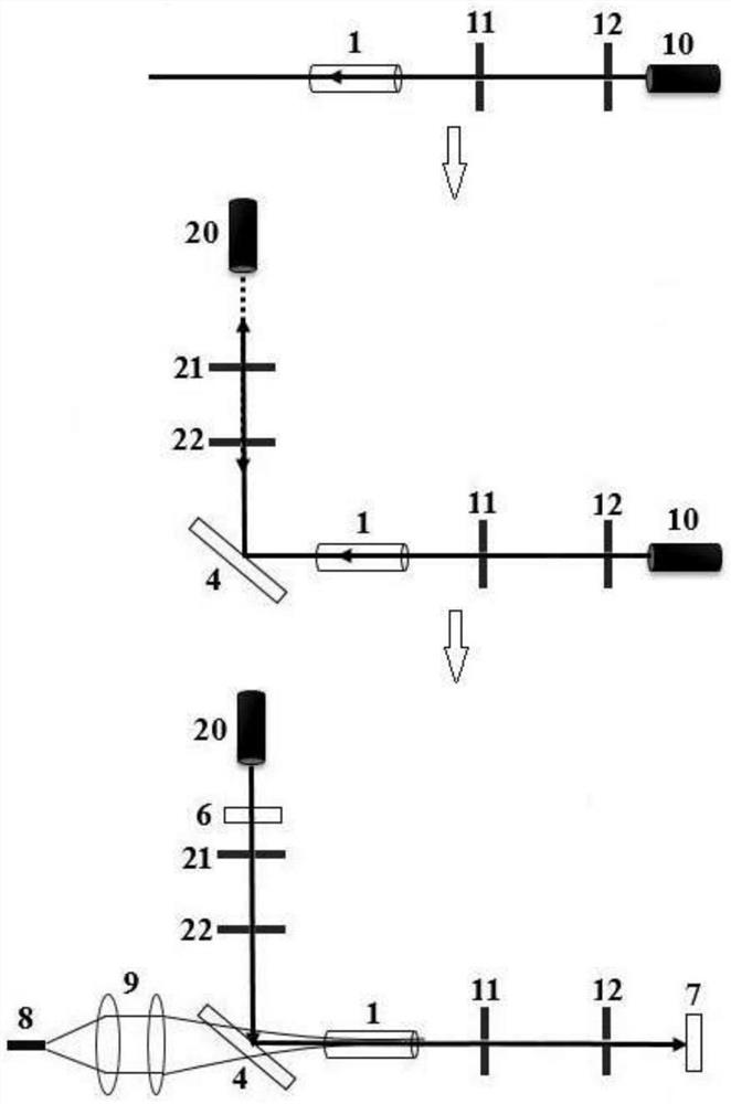
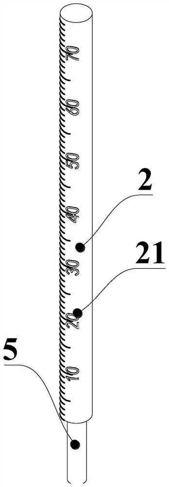
[0037] Such as figure 2 As shown, this embodiment provides an optical path calibration tool, which is suitable for quantum information-related optical experiments such as quantum communication and quantum measurement, and includes a fixed rod 5 and a calibration rod 2 coaxially arranged, and the diameter of the calibration rod 2 is the same as that of the The spot diameters are roughly the same; the fixed rod 5 can be plugged and fitted with the fixed hole of the optical table (not shown) in the axial direction, so that the calibration rod 2 is on the optical path to be calibrated and placed above the optical table.

[0038] Based on the above embodiments, the optical path calibration method provided in this embodiment includes the following steps:

[0039] Step A: Select a calibration rod 2 with the same diameter according to the spot size, and connect the selected calibration rod 2 to the fixed rod 5;

[0040] Step B: Insert the fixed rod 5 into the first section of the un...

Embodiment 2

[0057] refer to Figure 4 , in this embodiment, the optical path calibration tool also includes a mounting base 3 above the optical platform, the calibration rod 2 and the fixing rod 5 are vertically connected with the upper and lower end surfaces of the mounting base 3 respectively, and the fixing rod 5 is still in transition with the fixing hole at this time At this time, the diameter of the mounting base 3 is greater than the diameter of the fixing hole, thereby preventing the calibration tool from slipping from the fixing hole. The calibration rod 2 and the fixing rod 5 are coaxially arranged for optical path calibration. Since the mounting base 3 can be used to limit the position, the calibration rod 2 can be smaller than the diameter of the fixing hole, so Figure 4 The calibration tool shown is able to accommodate spots of arbitrary size.

[0058] The calibration method based on the calibration tool provided in this embodiment includes the following steps:

[0059] St...


PUM


Abstract

The invention provides a light path calibration tool, which comprises a fixing rod and a calibration rod which are coaxially arranged, the diameter of the calibration rod is approximately the same as that of a light spot to be calibrated, and the fixing rod can be axially inserted and matched with a fixing hole in the surface of an optical platform, so that the calibration rod is positioned on a light path to be calibrated and is placed above the optical platform. The invention further provides an optical path calibration method, and the optical path calibration tool is sequentially used from front to back to adjust the optical devices so as to calibrate the optical path. The calibration tool has the advantages that the fixing rod can be directly inserted into the fixing hole, screw connection is not needed, the calibration tool can be quickly inserted and pulled out in the use process, and use is convenient; the calibration result is judged by judging whether the light spot is completely covered by the calibration rod, and the light path calibration precision is high; and the calibration rod can be directly irradiated by a light spot to check whether the size is proper or not before an experiment, so that the calibration precision is prevented from being influenced by processing errors. The device is suitable for quantum information related optical experiments such as quantum communication and quantum measurement.

Description

technical field [0001] The invention relates to the technical field of optical path debugging, in particular to an optical path calibration tool and method. Background technique [0002] In optical experiments and related applications using point light sources, it is usually necessary for light to be vertically incident on certain optical lenses, especially in quantum optics experiments. The accuracy of optical path adjustment often directly affects the experimental results, so keep the alignment of the optical path , that is, there is no offset in the horizontal and vertical directions, which will be particularly important. The existing method for adjusting the alignment of the optical path is generally the multi-aperture method. For example, the invention patent application with the publication number CN104242029A discloses a method for quickly installing and adjusting the laser folded resonator, which discloses the method of using the aperture to calibrate the light; A d...

Claims


Application Information

Patent Timeline
Patent Type & Authority Applications(China)
IPC IPC(8): G02B27/34
CPCG02B27/34
Inventor 唐世彪王浩代云启
Owner QUANTUMCTEK
Why Eureka
Try Eureka