
Radiology department image diagnosis film reading device

A technology for radiology and film reading, applied in optical components, optics, instruments, etc., can solve the problems of inconvenient observation of two films, inconvenient portability of the film reading device, etc., to achieve convenient communication and observation, convenient comparative observation, and avoid rigidity The effect of collision

Pending Publication Date: 2021-01-15
山西白求恩医院
View PDF16 Cites 0 Cited by
  • Summary
  • Abstract
  • Description
  • Claims
  • Application Information

AI Technical Summary

Problems solved by technology

[0003] In the imaging diagnosis of the radiology department, it is necessary to use an image reading device to read the image. The existing image reading device can only be used in a fixed position. However, when the doctor needs to go out to see a doctor, the doctor needs to do it outside the department. When reading the film, the film reading device is inconvenient to carry
Especially when the doctor needs to compare and observe the two films, the existing film reading device is inconvenient to observe the two films at the same time

Method used


Image

  • Radiology department image diagnosis film reading device
  • Radiology department image diagnosis film reading device
  • Radiology department image diagnosis film reading device

Examples


Embodiment 1

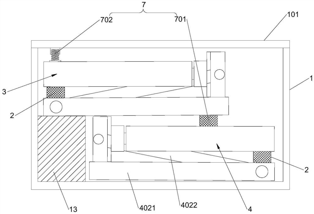
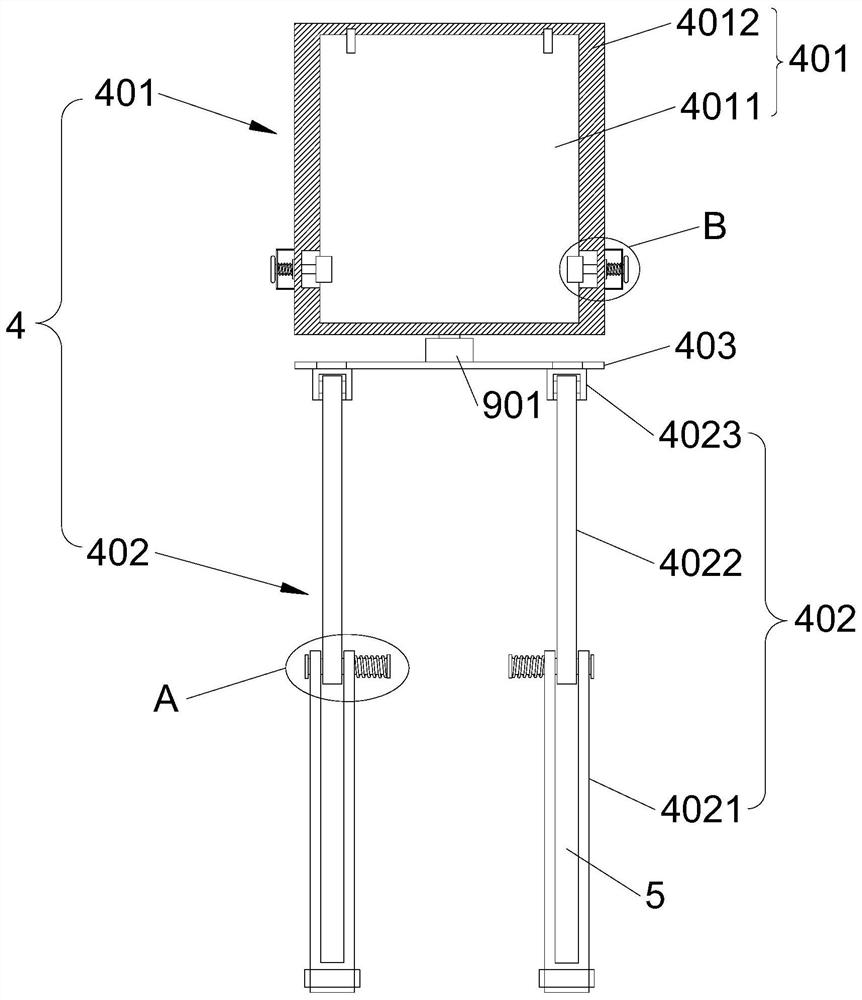
[0038] The radiology diagnostic image reading device of the present invention includes a box body 1, the box body 1 is hinged with a cover plate 101, and the first film reading unit 4 and the second film reading unit 4 that can be accommodated in the box body 1 are respectively arranged on both sides of the box body 1. Two original film units, the box body 1 is provided with a positioning assembly 7 for elastically supporting the first film reading unit 4 and the second film reading unit 3, the first film reading unit 4 and the second film reading unit 3 both include A sheet assembly 401 and a foldable support assembly 402 capable of being folded. The sheet reading assembly 401 includes a light-transmitting plate 4011 and a frame 4012. The light-transmitting plate 4011 is installed in the frame 4012. The upper end of the folded support assembly 402 is provided with a support plate 403. The support plate A rotating connection assembly 9 is provided between the frame 403 and the ...

Embodiment 2

[0041] This embodiment is further optimized on the basis of Embodiment 1 as follows: the folding support assembly 402 includes a first connecting rod 4021, a second connecting rod 4022 and a positioning block 4023, and the lower end of the first connecting rod 4021 is connected to the bottom of the box body 1 The wall is hinged, and the first connecting rod 4021 penetrates radially to form a receiving groove 5, the receiving groove 5 runs through the upper end of the first connecting rod 4021, and the lower end of the second connecting rod 4022 is located in the receiving groove 5 and is rotationally connected for positioning. The block 4023 is arranged on the lower end of the support plate 403 , and the upper end of the second connecting rod 4022 is connected to the positioning block 4023 in rotation.

[0042] After adopting the above technical solution: the lower end of the first connecting rod 4021 is hinged with the inner wall of the box body 1. During the process of foldin...

Embodiment 3

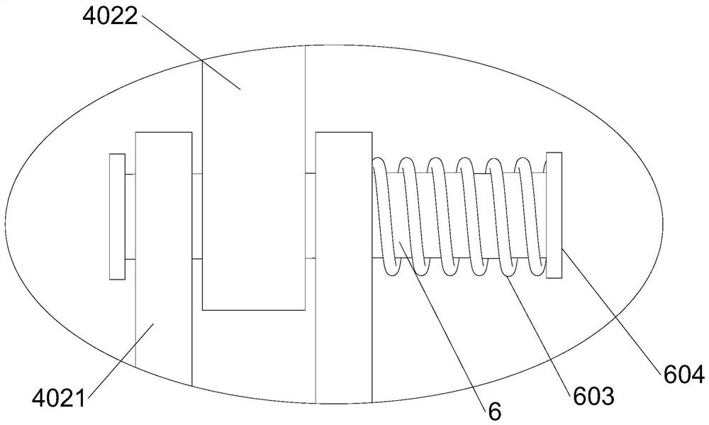
[0044] This embodiment is further optimized on the basis of Embodiment 1 as follows: the second connecting rod 4022 and the first connecting rod 4021 are penetrated with a coaxial through hole, and the cross-sectional shape of the inner wall of the through hole is a regular polygon. A locking rod 6 is provided through it. The locking rod 6 includes a locking section 601 and a guide section 602. The cross-sectional shape of the locking section 601 is adapted to the inner wall of the through hole, and the diameter of the guide section 602 is consistent with the inscribed circle of the through hole. The diameters are the same, both ends of the locking rod 6 are provided with baffles 604 , the guide section 602 is covered with a locking spring 603 , and the locking spring 603 is located between the baffle 604 and the outer wall of the first connecting rod 4021 .

[0045] After adopting the above technical scheme: the locking spring 603 is sleeved on the guide section 602 of the loc...


PUM


Abstract

The invention discloses a radiology department image diagnosis film reading device, and relates to the technical field of diagnosis image film reading devices. The film reading device comprises a boxbody, a cover plate is hinged to the box body, a first film reading unit and a second film reading unit which can be stored in the box body are arranged on the two sides of the interior of the box body respectively, and a positioning assembly used for elastically supporting the first film reading unit and the second film reading unit is arranged in the box body; the first film reading unit and thesecond film reading unit each comprise a film reading assembly and a foldable folding supporting assembly, each film reading assembly comprises a light-transmitting plate and a frame, the light-transmitting plates are installed in the frames, supporting plates are arranged at the upper ends of the folding supporting assemblies, and rotating connecting assemblies are arranged between the supporting plates and the frames; and each film reading assembly is also provided with a pressing assembly for elastically pressing the film. The film reading device can be stored and carried, occupies a smallspace, and is convenient for doctors to read films when going out for treatment or academic communication and the like; and the two films can be conveniently compared and observed at the same time.

Description

technical field [0001] The invention relates to the technical field of diagnostic image reading devices, in particular to a diagnostic image reading device for radiology. Background technique [0002] In the construction of modern hospitals, the radiology department is a department that integrates inspection, diagnosis and treatment. Many diseases in various clinical departments must be checked by radiology equipment to achieve a clear diagnosis and auxiliary diagnosis. [0003] In the imaging diagnosis of the radiology department, it is necessary to use an image reading device to read the image. The existing image reading device can only be used in a fixed position. However, when the doctor needs to go out to see a doctor, the doctor needs to do it outside the department. When reading the film, the film reading device is inconvenient to carry. Especially when the doctor needs to compare and observe the two films, the existing film reading device is inconvenient to observe ...

Claims


Application Information

Patent Timeline
IPC IPC(8): G02B27/02G02B27/04
CPCG02B27/024G02B27/028G02B27/04
Inventor 薛亮亮
Owner 山西白求恩医院
Learn More