
A kind of electroplating processing equipment

A technology for electroplating treatment and equipment, applied in the field of electroplating treatment equipment, can solve the problems of inconvenient operation of equipment, slow equipment, reduced equipment working efficiency, etc., and achieve the effects of improving working efficiency, fast cleaning, and preventing pollution

Inactive Publication Date: 2021-02-02
安徽兴宇金属实业有限公司
View PDF12 Cites 0 Cited by
  • Summary
  • Abstract
  • Description
  • Claims
  • Application Information

AI Technical Summary

Problems solved by technology

[0002] Electroplating technology has always been an excellent technology in terms of anti-corrosion and anti-rust of parts. There are many problems in the electroplating process, such as: the parts after electroplating are converted between different electrolytic cells due to their own reaction solution When it is used, the excess reaction solution will be brought into other electrolytic cells or chemical reaction cells, which will affect the corresponding electroplating effect and purity, and the existing equipment still has many problems in terms of insulation and equipment dexterity, such as : After the workpiece is lifted or lowered, the workpiece is reacted in the electrolytic cell. In this process, the existing equipment has relatively slow and unstable working steps, which reduces the working efficiency of the equipment and increases the labor burden of the personnel. increase, which to a large extent makes it inconvenient for people and equipment to work. Due to the emergence of the above problems, the practicability of existing electroplating treatment equipment is reduced, and it is urgent to improve

Method used


Image

  • A kind of electroplating processing equipment
  • A kind of electroplating processing equipment
  • A kind of electroplating processing equipment

Examples


Embodiment Construction

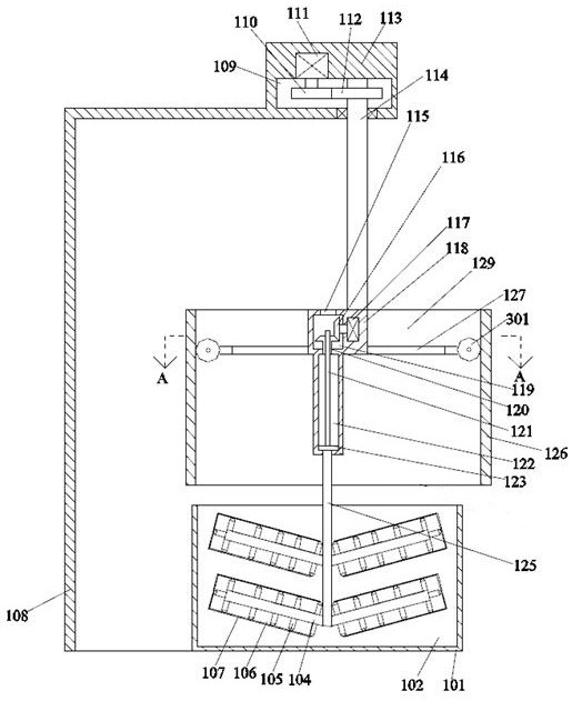
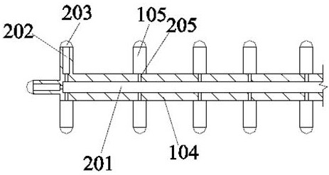
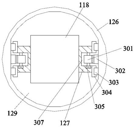
[0020] Such as Figure 1-Figure 3 As shown, the present invention is described in detail. For the convenience of description, the orientations mentioned below are now stipulated as follows: figure 1 The up, down, left, right, front and back directions of the projection relationship itself are consistent. A kind of electroplating treatment equipment of the present invention includes a support rod 108, and a transmission box 113 is fixed on the right end surface of the support rod 108. A driving device is arranged in the transmission box 113 to drive Below the device is an adjustment device for lifting and immersing the workpiece and removing excess reaction chemical solvents on the surface of the workpiece. The lower side of the adjustment device is provided with an electrolytic cell device for storing chemical solvents and facilitating chemical reactions.

[0021] Beneficially, wherein, the driving device includes a transmission cavity 109 arranged in the transmission box 113,...


PUM


Abstract

The invention discloses electroplating treatment equipment. A supporting rod is included. A transmission box is fixedly arranged on the right end face of the supporting rod. A drive device is arrangedin the transmission box. An adjusting device which is used for conducting lifting immersing on a workpiece and removing a surplus reaction chemical solvent on the surface of the workpiece is arrangedbelow the drive device, and the lower side of the adjusting device is provided with an electrolytic cell device used for containing the chemical solvent and facilitating the chemical reaction is arranged on the lower side of the adjusting device. The equipment is simple in structure, the design of the drive device, the adjusting device and the electrolytic cell device is adopted, by means of theequipment, the situation that when the workpiece is transferred between different procedures, other chemical solvents are brought to the next procedure can be prevented, and pollution of the chemicalsolvents of other procedures is prevented; and when the chemical solvent on the surface of the workpiece is cleaned, the purpose of rapid cleaning can be achieved, and the work efficiency of the equipment is greatly improved.

Description

technical field [0001] The invention relates to the technical field of electroplating equipment, in particular to electroplating treatment equipment. Background technique [0002] Electroplating technology has always been an excellent technology in terms of anti-corrosion and anti-rust of parts. There are many problems in the electroplating process, such as: parts after electroplating are converted between different electrolytic cells due to their own reaction solution When it is used, the excess reaction solution will be brought into other electrolytic cells or chemical reaction cells, which will affect the corresponding electroplating effect and purity, and the existing equipment still has many problems in terms of insulation and equipment dexterity, such as : After the workpiece is lifted or lowered, the workpiece is reacted in the electrolytic cell. In this process, the existing equipment has relatively slow and unstable working steps, which reduces the working efficienc...

Claims


Application Information

Patent Timeline
Patent Type & Authority Patents(China)
IPC IPC(8): C25D17/00
CPCC25D17/00
Inventor 不公告发明人
Owner 安徽兴宇金属实业有限公司
Learn More