A kind of magnetron sputtering optical coating equipment and coating method with vacuum mechanical arm

A magnetron sputtering, optical coating technology, applied in sputtering coating, vacuum evaporation coating, ion implantation coating and other directions, can solve the problems of affecting output, less coating, low target coating efficiency, etc., to achieve loading and unloading materials The effect of short time, improved stability and reduced pollution

Active Publication Date: 2019-11-12
沈阳中北真空技术有限公司
View PDF6 Cites 0 Cited by
  • Summary
  • Abstract
  • Description
  • Claims
  • Application Information

AI Technical Summary

Problems solved by technology

Magnetron sputtering optical coating equipment and magnetron sputtering optical coating methods have also appeared on the market, basically all of which are used in coating equipment and coating methods for decoration or molds, or for functional magnetron sputtering in solar or display devices. All of these films do not require precise control of film thickness, and there are few coatings; because the magnetron sputtering optical coating used in the field of optical and electronic devices is to precisely control the coating of multi-layer films under high-speed rotation, the highest coating needs Hundreds of layers of film achieve optical purposes by controlling the passage or reflection of light of different wavelengths; although there are technologies that can be coated with optical films, there are two major problems. The first is that the thickness of the coating cannot be monitored and controlled. Control the time and indirectly control the film thickness; secondly, only oxide targets can be used to directly coat metal oxides. Such targets have extremely low coating efficiency and are not suitable for mass production; therefore, it is necessary to develop magnetic materials suitable for mobile phones and other electronic equipment applications. Sputtering optical coating equipment and vacuum magnetron sputtering coating method applied in optical field
[0003] In the prior art, the vacuum magnetron sputtering coating equipment is single-chamber, and the vacuum needs to be broken every time, which not only affects the output, but when the gas is amplified, the surface of the magnetron sputtering target will absorb water vapor and undergo an oxidation reaction. Cause the pollution of magnetron sputtering target, have a strong impact on the performance of product and the consistency of product; For this reason the present invention has designed the magnetron sputtering optical coating equipment with the vacuum manipulator arm that does not destroy vacuum and finishes loading and unloading substrate and realized continuous Coating method; in order to improve the control accuracy of the coating thickness, the present invention is also provided with a crystal vibration film thickness measuring device

Method used


Image

  • A kind of magnetron sputtering optical coating equipment and coating method with vacuum mechanical arm
  • A kind of magnetron sputtering optical coating equipment and coating method with vacuum mechanical arm
  • A kind of magnetron sputtering optical coating equipment and coating method with vacuum mechanical arm

Examples


Embodiment Construction

[0032] The magnetron sputtering optical coating equipment and the magnetron sputtering optical coating method involved in the present invention will be described below with reference to the accompanying drawings.

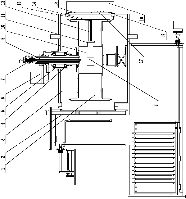
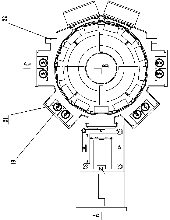
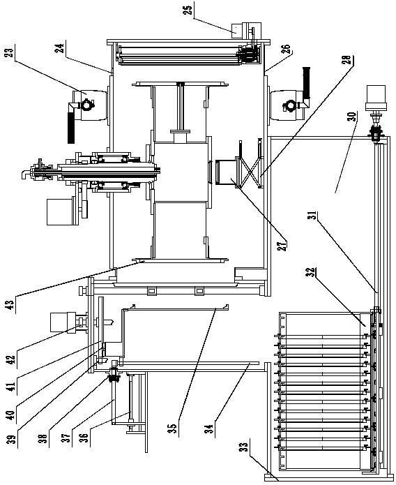
[0033] Such as Figures 1 to 3As shown, a magnetron sputtering optical coating equipment with a vacuum manipulator includes a vacuum coating chamber 3, a vacuum manipulator chamber 30, a magnetron sputtering target assembly 19, and a vertical rotating drum 1; the vacuum coating chamber 3 is a vertical Type cylindrical structure, upper and lower ends are provided with an upper cover 24 and a lower cover 26, and side doors 22 are arranged on the side; the vertical cylindrical side wall is also provided with an interface connected with the vacuum manipulator chamber 30; The vertical rotating drum 1 is located in the vacuum coating chamber 3 and rotates around the vertical axis. The center of the vertical rotating drum 1 is provided with a sealed box 10. The upper part ...


PUM

PropertyMeasurementUnit
thicknessaaaaaaaaaa

Abstract

The invention discloses a magnetron sputtering optical coating device with a vacuum mechanical arm and a coating method. The magnetron sputtering optical coating device comprises a vacuum coating chamber, a vacuum mechanical arm chamber, magnetron sputtering target assemblies and a vertical rotating drum, wherein a connector connected with the vacuum mechanical arm chamber is formed in the side wall of the vacuum coating chamber; the vertical rotating drum rotates around the vertical axis; a seal box is arranged at the center of the vertical rotating drum; the plurality of magnetron sputteringtarget assemblies are arranged on the side wall of the vacuum coating chamber on the periphery of the vertical rotating drum; the vacuum mechanical arm is arranged in the vacuum mechanical arm chamber; and the vacuum mechanical arm horizontally and vertically moves in the vacuum state. The coating method comprises the steps of vacuumizing the coating device, rotating the vertical rotating drum till the vertical rotating drum reaches set rotation speed, starting a radio-frequency ion source, alternately coating film layers of two materials according to technological requirements, clamping a substrate with a chip on the vertical rotating drum through the vacuum mechanical arm, and taking the coated substrate down from the vertical rotating drum.

Description

technical field [0001] The invention belongs to the field of vacuum equipment, and in particular relates to a magnetron sputtering optical coating device with a vacuum mechanical arm and a magnetron sputtering optical coating method applied in the field of optical and electronic devices. Background technique [0002] At present, the main coating equipment for optics and other high-thickness requirements is mainly vacuum evaporation coating. With the development of electronic equipment such as mobile phones, it is required not only high control precision of the film system, but also high production capacity and low cost. Magnetron sputtering optical coating equipment and magnetron sputtering optical coating methods have also appeared on the market, basically all of which are used in coating equipment and coating methods for decoration or molds, or for functional magnetron sputtering in solar or display devices. All of these films do not require precise control of film thickne...

Claims


Application Information

Patent Timeline
Patent Type & Authority Patents(China)
IPC IPC(8): C23C14/35C23C14/50C23C14/54
CPCC23C14/352C23C14/505C23C14/542
Inventor 孙宝玉陈晓东杨威力段永利
Owner 沈阳中北真空技术有限公司
Why Eureka
Try Eureka