Device and method for quantitatively simulating seam width dynamic change during temporary blocking in seam

A technology of dynamic change and slit width, applied in the direction of measuring devices, using stable tension/pressure test material strength, instruments, etc., can solve the problems of inability to simulate crack surface morphology and dynamic slit width changes, etc., to achieve quantification Effects of simulation and real-time monitoring of fracture width dynamic changes

Active Publication Date: 2019-08-13
CHINA UNIV OF PETROLEUM (BEIJING)
View PDF7 Cites 10 Cited by
  • Summary
  • Abstract
  • Description
  • Claims
  • Application Information

AI Technical Summary

Problems solved by technology

[0003] At present, the indoor experiment of the temporary plugging material combination in the fracture mainly adopts the fixed fracture width technology, which cannot simulate the two key processes of the fracture surface morphology and the dynamic fracture width change, and lacks the quantitative simulation device and method for the fracture process

Method used


Image

  • Device and method for quantitatively simulating seam width dynamic change during temporary blocking in seam
  • Device and method for quantitatively simulating seam width dynamic change during temporary blocking in seam
  • Device and method for quantitatively simulating seam width dynamic change during temporary blocking in seam

Examples


Embodiment 1

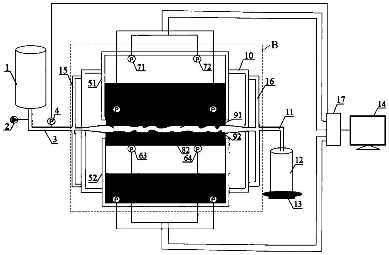
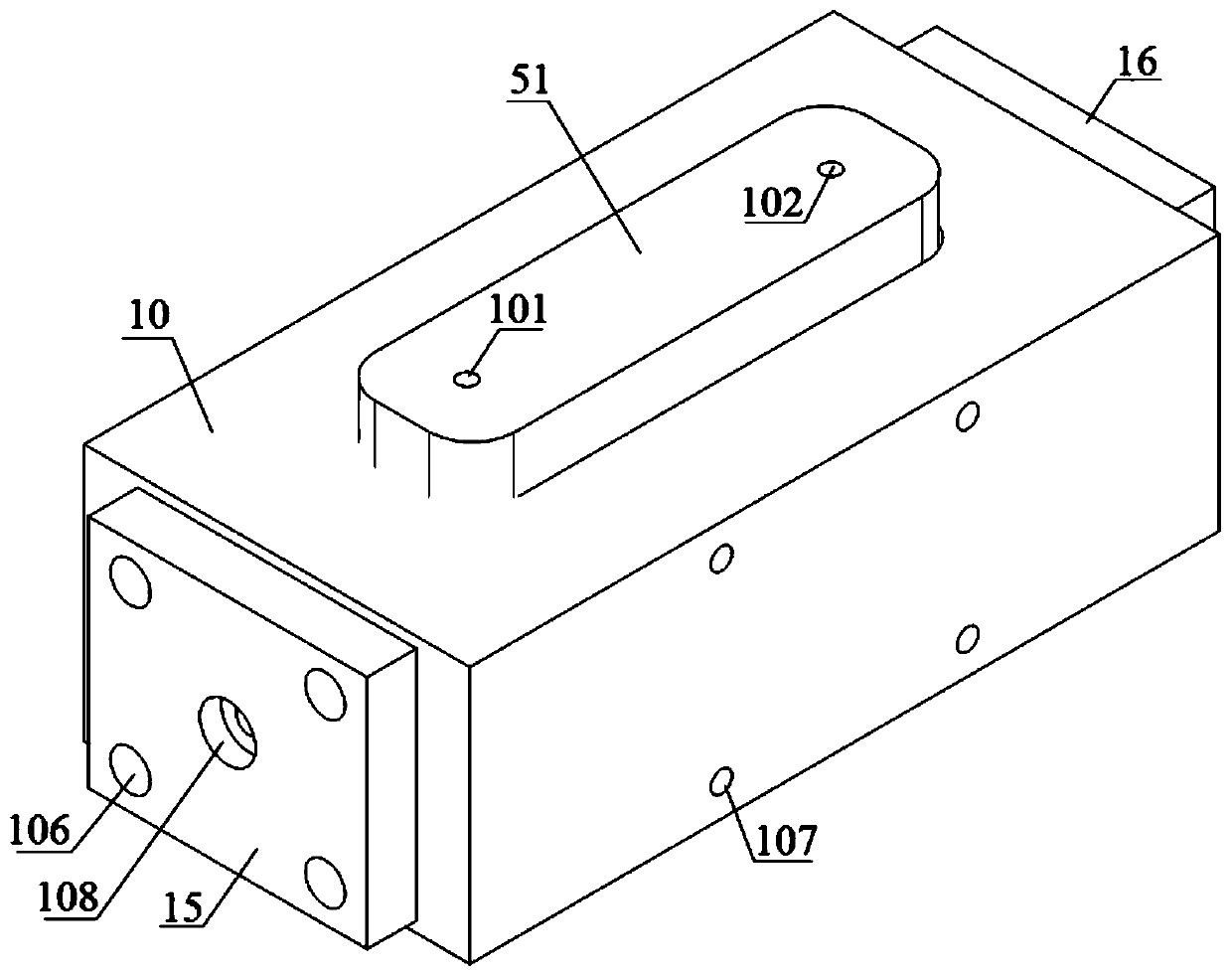
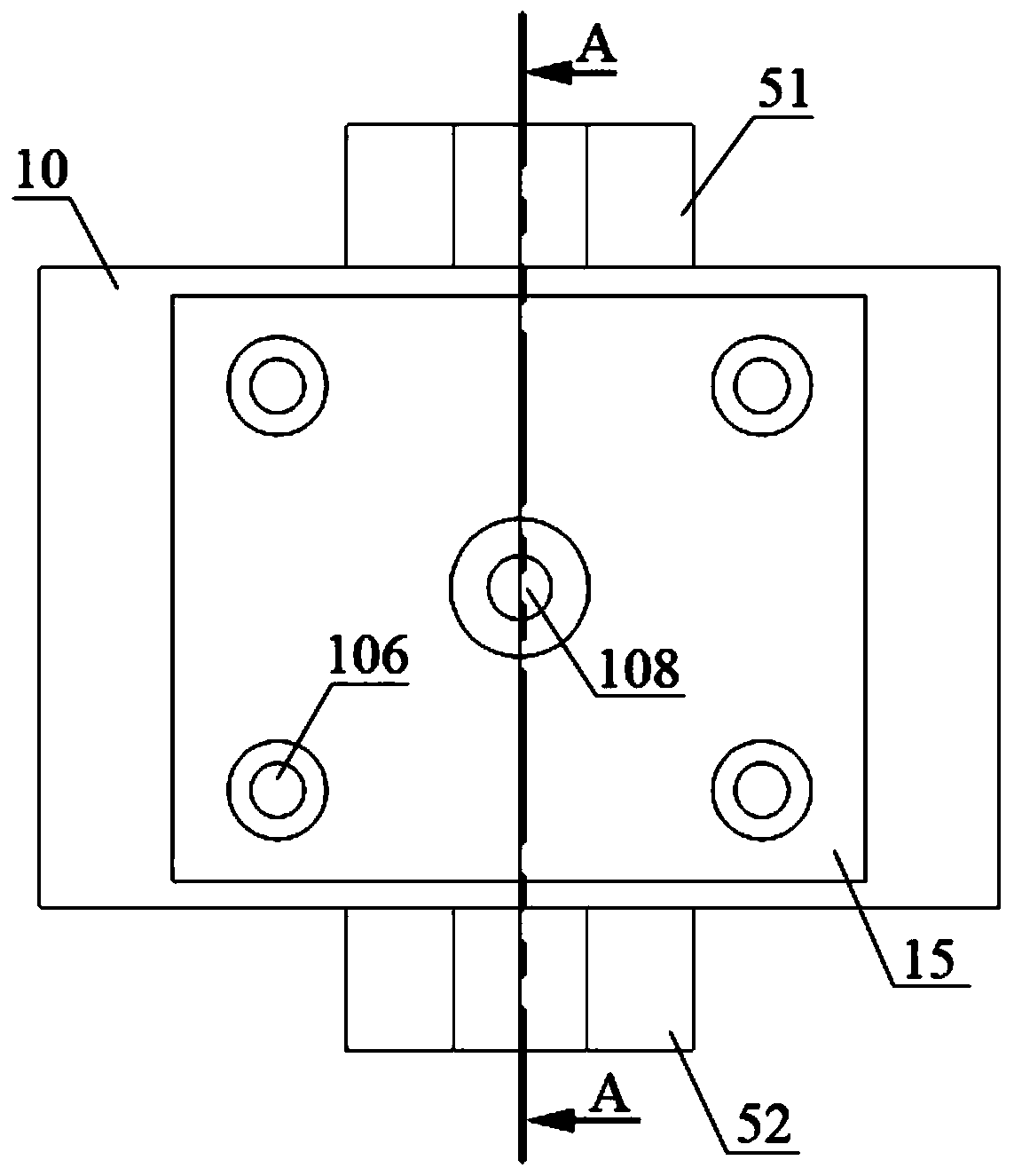
[0074] This embodiment provides a device for quantitatively simulating the dynamic change of the fracture width when the fracture is temporarily blocked, such as figure 1 , figure 2 , image 3 and Figure 4 As shown, the device includes:

[0075] The first chamber 51, the second chamber 52, the first piston 81, the second piston 82, the first 3D printing fracture surface 91, the second 3D printing fracture surface 92, the monitoring and processing system, the liquid injection system and the liquid collection system;

[0076] The inner surface of the first piston 81 is used to seal the first chamber 51, and the first piston 81 can perform piston movement in the first chamber 51; the inner surface of the second piston 82 is used to seal the second chamber 52, And the second piston 82 can perform piston movement in the second chamber 52; the first chamber 51 and the second chamber 52 are used to load the mixed phase;

[0077] One side of the first 3D printed crack surface 91...

Embodiment 2

[0091] This embodiment provides a method for quantitatively simulating the dynamic change of the fracture width when the fracture is temporarily blocked, and the method includes the following steps:

[0092] Step 1, according to the Young's modulus E of the target layer rock f , horizontal stress difference σ H -σ h , the pressure in the seam P inj and seam height H f Calculation of fracture width w under formation conditions f ;Calculated as follows:

[0093] f(w f ) = f(σ H -σ h ,E f , H f , P inj );

[0094] Among them, σ H is the maximum horizontal stress of the target layer, σ h is the minimum horizontal stress of the target layer;

[0095] In this implementation, temporary plugging and diversion fracturing is carried out for layer F of well A in an oilfield in the west, in-situ stress and rock mechanics parameters are obtained through well logging interpretation, and the formation pressure of layer F is obtained through well test data. The following is the...


PUM


Abstract

The invention provides a device and method for quantitatively simulating the seam width dynamic change during temporary blocking in a seam. The device comprises a first chamber, a second chamber, a first piston, a second piston, a first 3D printing crack surface, a second 3D printing crack surface, a monitoring processing system, a liquid injection system and a liquid collection system. Accordingto the method, fracturing liquid and / or a temporary blocking agent is injected into a crack channel through the liquid injection system, the pressure in a mixed phase chamber is monitored in real time, and the seam width dynamic change in the process of temporary blocking in the seam is monitored in real time through the monitoring processing system. By adopting the device and the method, the typeand proportion of mixed phases in the mixed phase chamber can be designed according to reservoir rock mechanical properties and in-situ stress parameters, fine simulation of reservoir rock mechanicsand stress characteristics is achieved, then temporary blocking in the seam under the reservoir condition reappears, and the seam width dynamic change in the process of temporary blocking in the seamis quantitatively simulated and monitored in real time.

Description

technical field [0001] The invention belongs to the field of petroleum and natural gas engineering, and relates to a device and method for quantitatively simulating the dynamic change of the fracture width when the fracture is temporarily blocked. Background technique [0002] Temporary plugging diversion fracturing technology refers to pumping a certain amount of temporary plugging material to “plug” the primary fractures after hydraulic fracturing to open the primary fractures, thereby increasing the net pressure in the fractures and forcing the fractures to Turn to form new fractures, and the pumped temporary plugging materials will self-degrade under the formation temperature and pressure conditions, and the conductivity of all fractures will be restored, thereby increasing the productivity of oil and gas wells. At present, this technology is widely used in the reconstruction of tight oil and gas wells in Xinjiang, Tarim, Qinghai and Changqing in my country. The pluggin...

Claims


Application Information

Patent Timeline
Patent Type & Authority Applications(China)
IPC IPC(8): G01N3/12G01B21/02
CPCG01B21/02G01N3/12
Inventor 李卉李奔周福建杨凯侯吉瑞曹乐乐
Owner CHINA UNIV OF PETROLEUM (BEIJING)
Why Eureka
Try Eureka