
Welding tool positioning structure and positioning method

A welding tooling and positioning structure technology, applied in welding equipment, auxiliary welding equipment, welding/cutting auxiliary equipment, etc., can solve the problems of fixing and precise positioning of parts that cannot be processed

Pending Publication Date: 2019-08-16
YUNNAN LIFAN JUNMA AUTOMOBILE
View PDF0 Cites 1 Cited by
  • Summary
  • Abstract
  • Description
  • Claims
  • Application Information

AI Technical Summary

Problems solved by technology

[0003] The purpose of the embodiment of the present application is to provide a welding tool positioning structure and positioning method, aiming at improving the problem that the processing parts cannot be fixed and accurately positioned during welding

Method used


Image

  • Welding tool positioning structure and positioning method
  • Welding tool positioning structure and positioning method
  • Welding tool positioning structure and positioning method

Examples


Embodiment Construction

[0031] In order to make the purpose, technical solutions and advantages of the embodiments of the application clearer, the technical solutions in the embodiments of the application will be clearly and completely described below in conjunction with the accompanying drawings in the embodiments of the application. Obviously, the described embodiments It is a part of embodiment of this application, and is not all embodiment. Based on the implementation manners in this application, all other implementation manners obtained by persons of ordinary skill in the art without creative efforts fall within the scope of protection of this application.

[0032] Accordingly, the following detailed description of the embodiments of the application, provided in the accompanying drawings, is not intended to limit the scope of the claimed application, but merely represents selected embodiments of the application. Based on the implementation manners in this application, all other implementation ma...


PUM


Abstract

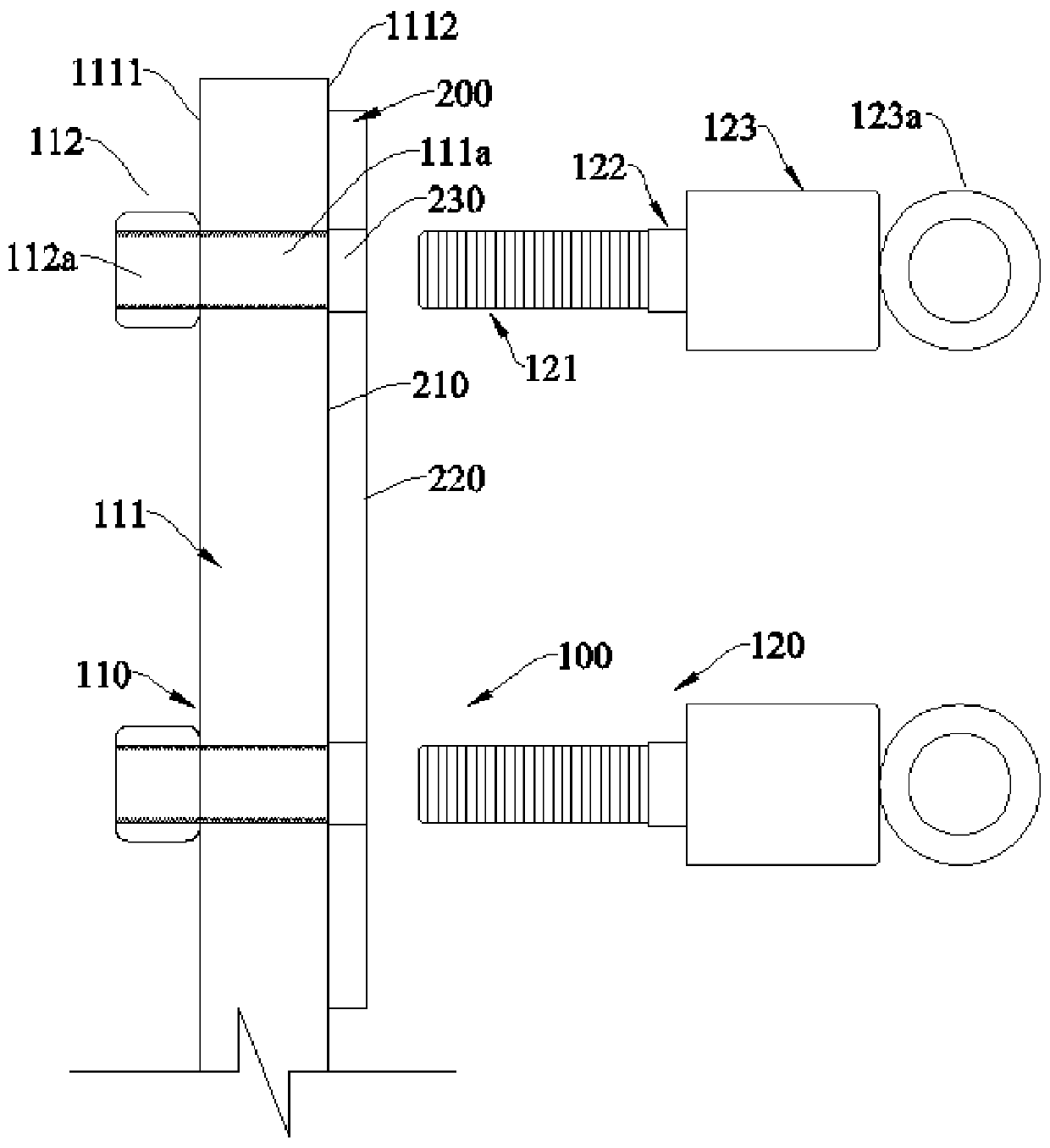
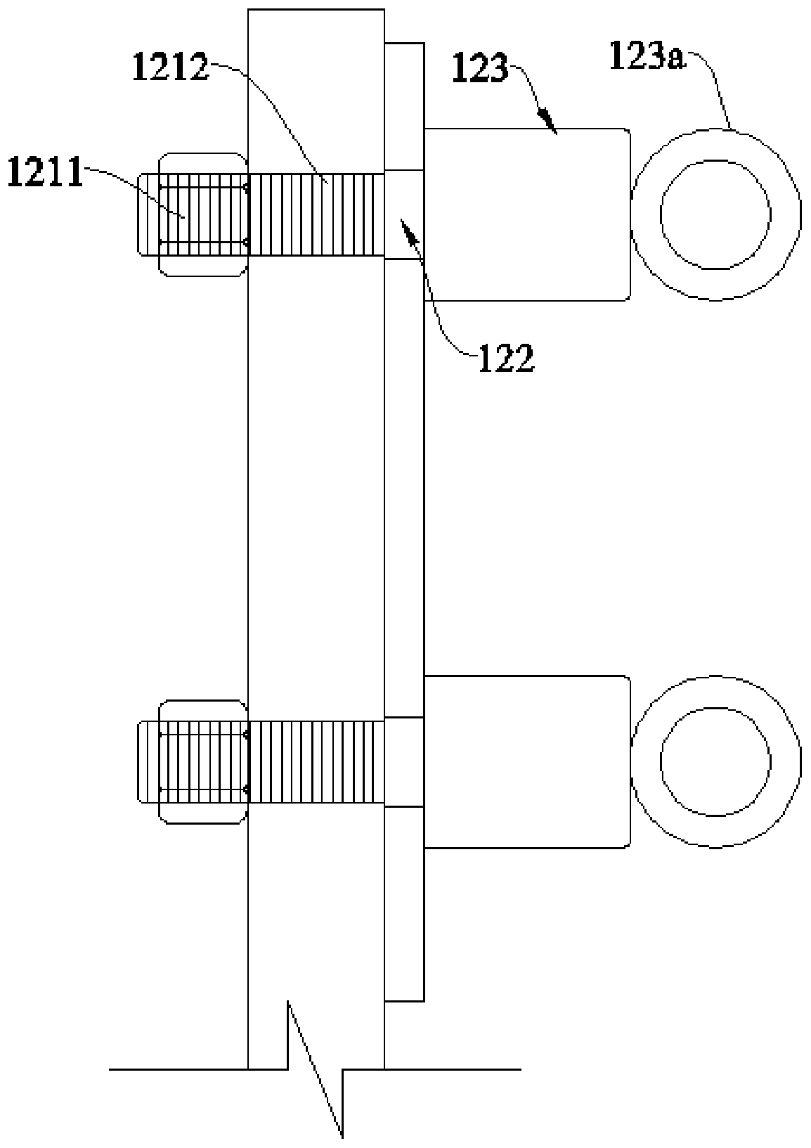
The embodiment of the invention provides a welding tool positioning structure and a positioning method, and relates to the technical field of welding positioning. The welding tool positioning structure comprises a positioning part and a locking part, the positioning part is provided with a mounting hole, the locking part and the positioning part can clamp a machining part, one surface of the machining part is attached to the surface of the positioning part, the machining part is provided with a positioning hole, the locking part comprises a first connecting segment, a second connecting segmentand a third connecting segment which are connected in sequence, during connection, the second connecting segment and the positioning hole are in transition fit, the second connecting segment abuts against the surface of the positioning part, the third connecting segment abuts against the surface of the machining part, the first connecting segment and the hole wall of the mounting hole are in threaded connection, and the machining part and the positioning part are locked.

Description

technical field [0001] The present application relates to the technical field of welding positioning, in particular, to a welding tool positioning structure and positioning method. Background technique [0002] When welding processed parts, the traditional method is to carry out simple matching manually. Since the processed parts are usually manually carried out simple matching, this method cannot fix and accurately position the processed parts, resulting in stability and The accuracy of welding cannot be guaranteed, and the processed parts after welding cannot meet the requirements. Contents of the invention [0003] The purpose of the embodiment of the present application is to provide a positioning structure and positioning method of a welding tool, aiming at improving the problem of inability to fix and accurately position the processed parts during welding. [0004] In a first aspect, an embodiment of the present application provides a welding tool positioning struct...

Claims


Application Information

Patent Timeline
Patent Type & Authority Applications(China)
IPC IPC(8): B23K37/04
CPCB23K37/04
Inventor 马李斌龙云朗李志刚
Owner YUNNAN LIFAN JUNMA AUTOMOBILE
Learn More