Machining and punching equipment for plastic plate

A technology of mechanical processing and plastic sheet, which is applied in metal processing and other directions, can solve the problem of difficult processing and punching of foam plastic sheet, and achieve the effect of promoting the effect of reciprocating sliding

Inactive Publication Date: 2019-08-16
LINAN LEILUO PLASTIC FACTORY
View PDF9 Cites 2 Cited by
  • Summary
  • Abstract
  • Description
  • Claims
  • Application Information

AI Technical Summary

Problems solved by technology

[0003] The purpose of the present invention is to solve the problem that the foamed plastic board is difficult to process and punch holes and propose a kind of punching equipment for mechanical processing of plastic boards

Method used


Image

  • Machining and punching equipment for plastic plate
  • Machining and punching equipment for plastic plate
  • Machining and punching equipment for plastic plate

Examples


Embodiment 1

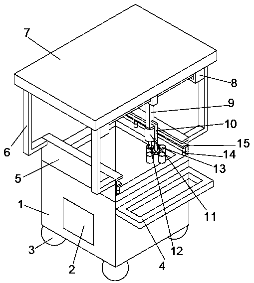
[0029] Embodiment 1: refer to figure 1 ;

[0030] A punching device for mechanical processing of plastic sheets, comprising a waste collection box 1 and a control panel 2, the left side of the waste collection box 1 is provided with an opening for waste cleaning, and the middle part of the front side of the waste collection box 1 is fixed to the control panel 2 Connection, the bottom of the waste collection box 1 is fixedly equipped with shifting wheels 3 for easy movement, the top of the right side of the waste collection box 1 is fixedly connected with a push handle 4, and the upper port of the waste collection box 1 is fixedly connected with the bottom surface of the fixed seat 5 along the surface. The middle part of the seat 5 is provided with a through opening, the front and rear sides of the fixed seat 5 are provided with card slots, the bottom surface of the card slot groove is fixedly equipped with an electric control telescopic rod 14, and the upper end of the electri...

Embodiment 2

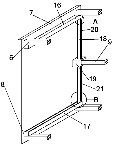
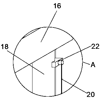
[0034] Embodiment 2: refer to Figure 2-5 , the basis of the embodiment 1 is different in that;

[0035] The moving device 8 includes a first chute 16 and a second chute 17, the first chute 16 is fixedly connected to one side of the bottom surface of the support plate 7, the second chute 17 is fixedly connected to the other side of the bottom surface of the support plate 7, and the second chute 17 is fixedly connected to the other side of the bottom surface of the support plate 7. The chute 17 is slidably connected with one end of the sliding connecting rod 18, and the other end of the sliding connecting rod 18 is slidably connected with the first chute 16 through an electric control drive block, and the outer surface of the middle part of the sliding connecting rod 18 is slidably connected with a connecting block 19. The lower side is fixedly connected with the upper end of the connecting rod 9, and one end of the sliding connecting rod 18 is fixedly installed with a micromot...

Embodiment 3

[0038] Embodiment 3: refer to Figure 6-8 , the basis of the embodiment 1 is different in that;

[0039] The adjusting tool device 13 includes a driving swivel base 24, the driving swivel base 24 is electrically connected to the control panel 2, the upper surface of the driving swivel base 24 is fixedly connected with the vertical end of the L-shaped connecting rod 10, and the peripheral surface of the driving swivel base 24 is fixedly connected. There are multiple groups of connecting rods 25, the outer ends of the connecting rods 25 are fixedly connected with a supporting sleeve 26, the lower opening of the supporting sleeve 26 is provided with a retaining ring 27, the upper surface of the retaining ring 27 is fixedly connected with a spring 28, and the upper end of the spring 28 is connected with the extruding block 29 lower surfaces are fixedly connected around, the extrusion block 29 peripheral surfaces are slidingly connected with the support sleeve 26 inner walls, the m...


PUM


Abstract

The invention discloses machining and punching equipment for a plastic plate, and belongs to that field of plastic punching equipment. The machining and punching equipment comprises a waste collectionbox and a control panel; the waste collection box is connected with the control panel; movable wheels are mounted at the bottom of the waste collection box; the right side of the waste collection boxis connected with a pushing handle; the upper end of the waste collection box is connected with a fixed seat; the fixed seat is provided with a through opening; clamping grooves are formed in the twosides of the fixed seat; electric control telescopic rods are mounted in the clamping grooves; clamping plates are connected with the electric control telescopic rods; the front outer surface and therear outer surface of the fixed seat are connected with L-shaped supporting rods; the L-shaped supporting rods are connected with a supporting plate; a moving device is mounted on the supporting plate; the moving device is connected with a connecting rod; the connecting rod is connected with an air cylinder; the air cylinder sleeves an air pressure rod; the connecting rod is connected with an L-shaped connecting rod; and the L-shaped connecting rod is connected with a cutter adjusting device. The machining and punching equipment can realize fast and accurate punching of the plastic plate, isconvenient to operate and improves production efficiency.

Description

technical field [0001] The invention relates to the field of plastic punching equipment, in particular to a punching equipment used for machining plastic plates. Background technique [0002] At present, foamed plastic boards are widely used in packaging materials. Most of the foamed plastic products used for packaging are formed by molding. It is necessary to design and process the mold according to the shape of the product, and then use the foamed plastic raw material to produce a certain shape through the mold. Foam plastic products, the shape of the product is controlled by the mold. Not only the mold design of this foamed plastic product is cumbersome and expensive, but also the mold needs to be redesigned if its shape changes slightly, and its adaptability is not strong. For this reason, how to process the existing foamed plastic materials into packaging products of a certain shape in a low-cost and simple way has become the research focus of the industry. In additio...

Claims


Application Information

Patent Timeline
Patent Type & Authority Applications(China)
IPC IPC(8): B26F1/14B26D5/06B26D5/12B26D7/00B26D7/02B26D7/26
CPCB26D5/06B26D5/12B26D7/00B26D7/025B26D7/2628B26D2007/0018B26F1/14
Inventor 费小娟吴宏波胡先武
Owner LINAN LEILUO PLASTIC FACTORY
Why Eureka
Try Eureka