
COF automatic aligning, press-jointing and lightening structure

An automatic alignment and automatic technology, applied in the direction of lamination, lamination device, layered products, etc., can solve the problem of inaccurate alignment and crimping, and achieve the effect of saving manpower and time and accurate crimping

Pending Publication Date: 2019-08-16
SHENZHEN SKING INTELLIGENT EQUIP
View PDF0 Cites 1 Cited by
  • Summary
  • Abstract
  • Description
  • Claims
  • Application Information

AI Technical Summary

Problems solved by technology

[0005] The purpose of the present invention is to provide a COF automatic alignment and crimping lighting structure, aiming to solve the problem in the prior art that the accurate alignment and crimping cannot be performed when the flexible circuit board and the glass sheet are crimped

Method used


Image

  • COF automatic aligning, press-jointing and lightening structure
  • COF automatic aligning, press-jointing and lightening structure
  • COF automatic aligning, press-jointing and lightening structure

Examples


Embodiment Construction

[0023] In order to make the object, technical solution and advantages of the present invention clearer, the present invention will be further described in detail below in conjunction with the accompanying drawings and embodiments. It should be understood that the specific embodiments described here are only used to explain the present invention, not to limit the present invention.

[0024] The implementation of the present invention will be described in detail below in conjunction with specific embodiments.

[0025] In the drawings of this embodiment, the same or similar symbols correspond to the same or similar components; The indicated orientation or positional relationship is based on the orientation or positional relationship shown in the drawings, and is only for the convenience of describing the present invention and simplifying the description, rather than indicating or implying that the referred device or element must have a specific orientation, or in a specific orien...


PUM


Abstract

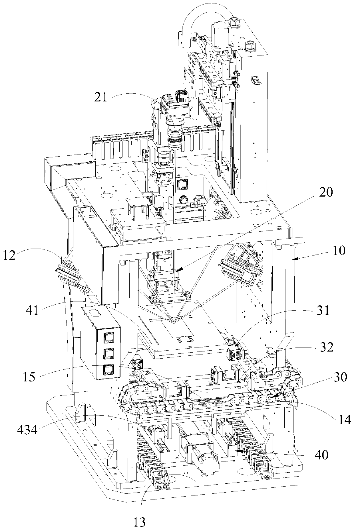
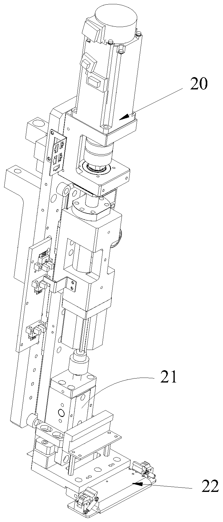
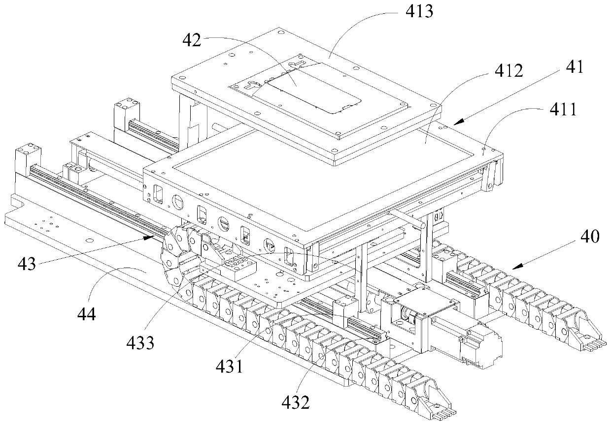
The invention relates to the technical field of aligning press-jointing equipment, and discloses a COF automatic aligning, press-jointing and lightening structure, which comprises a rack. A press-jointing assembly, an aligning assembly, and an automatic correcting assembly are arranged on the rack. The press-jointing assembly comprises a press head mechanism. A flexible printed circuit board is arranged on the press head mechanism. The aligning assembly is provided with a plurality of aligning cameras. The aligning cameras are opposite to the flexible printed circuit board and are used to shoot and position the datum points of the flexible printed circuit board. The automatic correcting assembly is arranged under the aligning assembly and the press-jointing assembly and is provided with amovable automatic correcting platform. A glass slice is placed on the automatic correcting platform. The aligning cameras shoot and position the datum points of the glass slice. The automatic correcting assembly will automatically adjust the position of the automatic correcting platform according to the positions of the datum points of the glass slice and the flexible printed circuit board obtained by the aligning cameras; the glass slice and the flexible printed circuit board are aligned, and then the press head mechanism is pressed down to laminate the glass slice and the flexible printed circuit board.

Description

technical field [0001] The patent of the present invention relates to the technical field of alignment crimping equipment, specifically, to a COF automatic alignment crimping lighting structure. Background technique [0002] COF, often called chip-on-chip film, fixes the driver IC on the flexible circuit board. It is a soft film construction technology that uses a soft additional circuit board as a packaged chip carrier to bond the chip with the flexible substrate circuit, or a single finger. Soft additional circuit boards for unpackaged chips also often refer to related products that apply COF technology. [0003] At present, the use of COF technology to crimp the flexible circuit board and the glass sheet is carried out by automatic or semi-automatic crimping equipment, which saves a lot of manpower and time, especially when the flexible circuit board and the glass sheet are crimped. When there is a large demand for crimping, it can be quickly completed by the equipment. ...

Claims


Application Information

Patent Timeline
Patent Type & Authority Applications(China)
IPC IPC(8): B32B37/10
CPCB32B37/10
Inventor 黄奕宏秦超尹国伟陈锦杰王卫武杨杰庄庆波韩宁宁刘驰
Owner SHENZHEN SKING INTELLIGENT EQUIP
Learn More