Supercharge Your Innovation With Domain-Expert AI Agents!

Woodworking engraving machine

A kind of engraving machine and woodworking technology, which is applied in the direction of engraving, wood processing equipment, processing models, etc. It can solve the problems of dust and scraps being inhaled into the nose by mistake, the scraps cannot be blown away, and the physical hazards of personnel, etc., so as to reduce the residual rate, Reduce the rate of aspiration and ensure your health

Active Publication Date: 2019-08-16
山东钠铭高激光设备有限公司
View PDF7 Cites 3 Cited by
  • Summary
  • Abstract
  • Description
  • Claims
  • Application Information

AI Technical Summary

Problems solved by technology

[0006] The present invention can solve the problem that a large amount of scraps will be generated during the engraving process of the existing engraving machine. People usually hold spray guns to blow off the scraps. During the blowing-off process, it is easy to cause dust and scraps to rise. The scraps are inhaled into the nose by mistake, which will cause harm to the body of the personnel. The scraps cannot be completely blown away with the spray gun, and some scraps will accumulate in the engraving groove to form a scrap layer. When the engraving machine is further engraved, it is easy to mistake the scrap layer for a board The material layer thus engraves the material chip layer, resulting in problems such as the depth of the engraving groove after complete engraving is less than the preset depth

Method used


Image

  • Woodworking engraving machine
  • Woodworking engraving machine
  • Woodworking engraving machine

Examples


Embodiment Construction

[0031] Embodiments of the present invention will be described below with reference to the drawings. In the process, in order to ensure the clarity and convenience of illustration, we may exaggerate the width of the lines or the size of the constituent elements in the diagram.

[0032] In addition, the following terms are defined based on the functions in the present invention, and may be different according to the user's or operator's intention or practice. Therefore, these terms are defined based on the entire content of this specification.

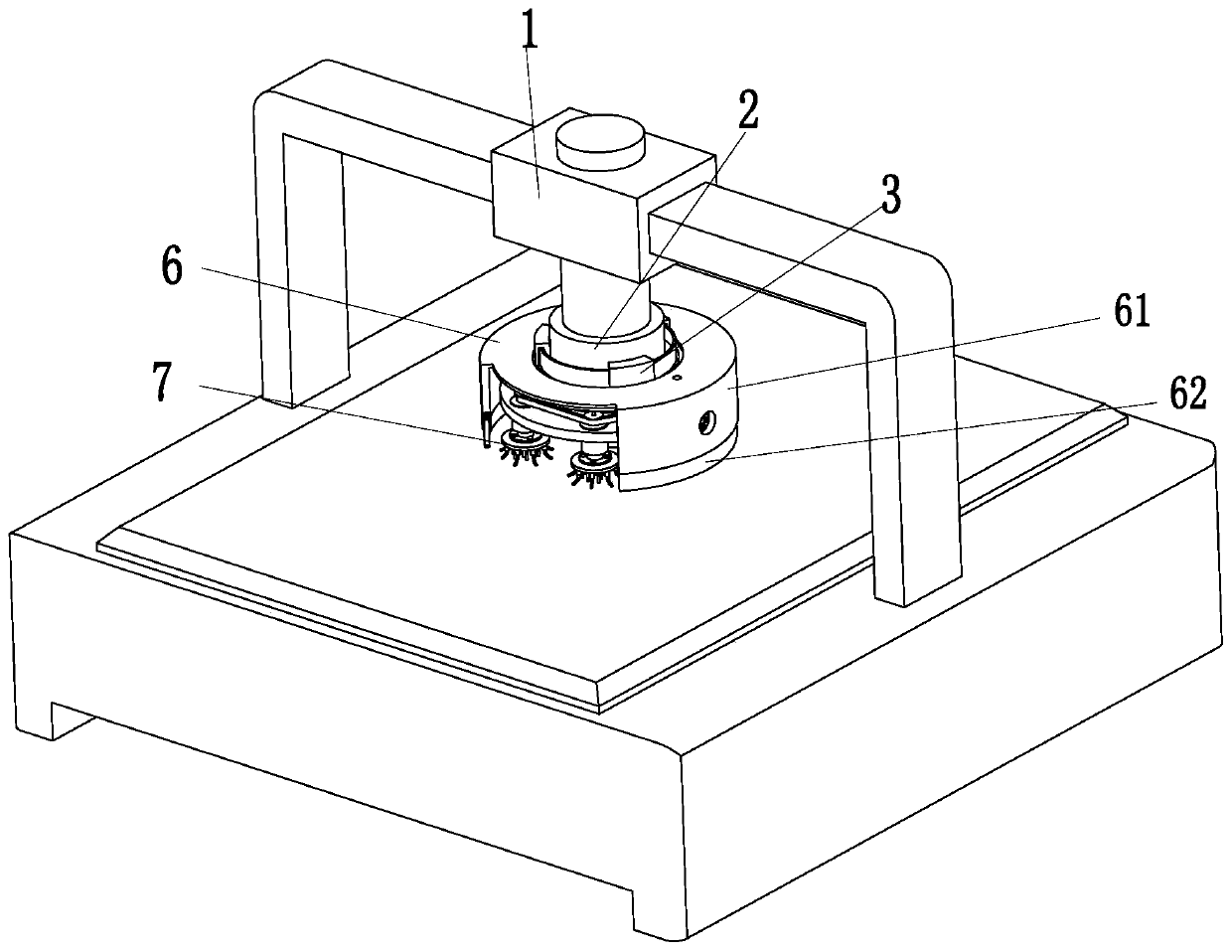
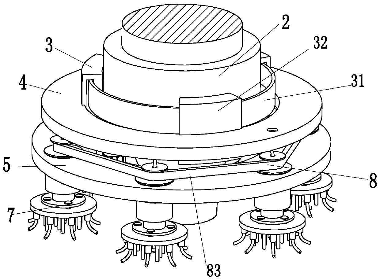
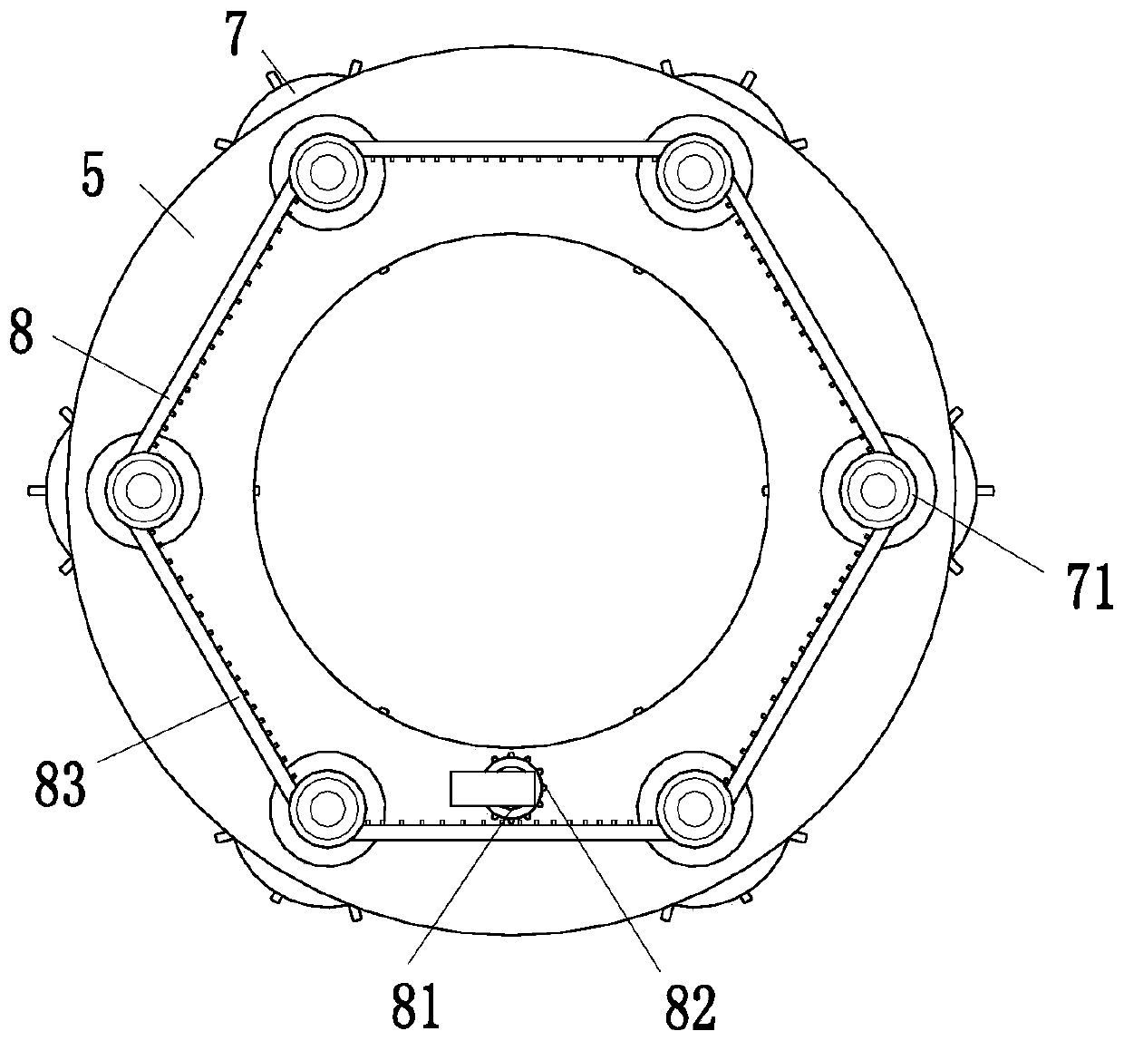
[0033] Such as Figure 1 to Figure 5 As shown, a woodworking engraving machine includes a machine tool body 1, an engraving head 2, a detachable frame 3, an air intake frame 4, a circular plate 5, a dust suction cover 6, a chip cleaning device 7 and a driving device 8, the described The engraving head 2 is installed on the machine tool body 1, the outer wall of the engraving head 2 is provided with a detachable frame 3, the middle part...


PUM


Abstract

The invention discloses a woodworking engraving machine. The woodworking engraving machine comprises a machine tool body, an engraving head, a detachable frame, an air inlet frame and a round plate, adust suction cover, a scrap removing device and a driving device, wherein the engraving head is arranged on the machine tool body, and the detachable frame is arranged on the outer wall of the engraving head. The middle of the detachable frame is provided with an air inlet frame, and the upper end of the air inlet frame is provided with a dust suction cover. The detachable frame is arranged on the round plate, the driving device is arranged at the upper end of the round plate, and scrap removing devices are uniformly arranged at the lower end of the round plate along the circumferential direction of the round plate. In the engraving process of an existing engraving machine, when a large amount of scraps can be generated, people usually blow the scraps away with a spray gun. During the blowing-off process, dust and scraps can be easily raised, the spray gun can not blow off all material scraps, and part of scraps are accumulated in an engraving groove to form a material chip layer. When the existing engraving machine further engraves, the material chip layer is easily mistaken as a plate material layer and is engraved, thus the depth of the engraving groove after completely engraving is smaller than the preset depth. According to the woodworking engraving machine, the problems described above can be solved.

Description

technical field [0001] The invention relates to the field of woodworking engraving equipment, in particular to a woodworking engraving machine. Background technique [0002] Woodworking engraving machine is a kind of machine for processing wood, mainly for wood engraving, used for engraving and milling on PVC, acrylic, plexiglass, two-color board, engineering plastics, bakelite, solid wood, etc., as well as soft metal materials, graphite The processing of electrodes is also suitable for engraving PCB circuit boards, generation wood model abrasive tools, and handicrafts. Woodworking engraving machines are mainly for wood carving, mainly solid wood and wood composite materials. Woodworking engraving machines often encounter the following problems during the engraving process: [0003] 1. A large amount of scraps will be produced during the engraving process. People usually hold a spray gun to blow off the scraps. During the process of blowing away, it is easy to cause dust an...

Claims


Application Information

Patent Timeline
IPC IPC(8): B44B1/00B44B1/06B44B3/00B44B3/06B27G3/00
CPCB27G3/00B44B1/00B44B1/06B44B3/00B44B3/06B44B3/061
Inventor 郭五连荣志强邵可心
Owner 山东钠铭高激光设备有限公司
Features
  • R&D
  • Intellectual Property
  • Life Sciences
  • Materials
  • Tech Scout
  • Unparalleled Data Quality
  • Higher Quality Content
  • 60% Fewer Hallucinations
Learn More