Self-winding device for charging pile

A winding device and charging pile technology, which is applied in the field of self-winding devices, can solve the problems that the charging gun cable cannot be wound and collected, the service life of the charging pile is reduced, and the cable is worn, so as to reduce maintenance costs, improve service life, and facilitate The effect of charging

Pending Publication Date: 2019-08-16
合肥旺和电子科技有限公司
View PDF0 Cites 2 Cited by
  • Summary
  • Abstract
  • Description
  • Claims
  • Application Information

AI Technical Summary

Problems solved by technology

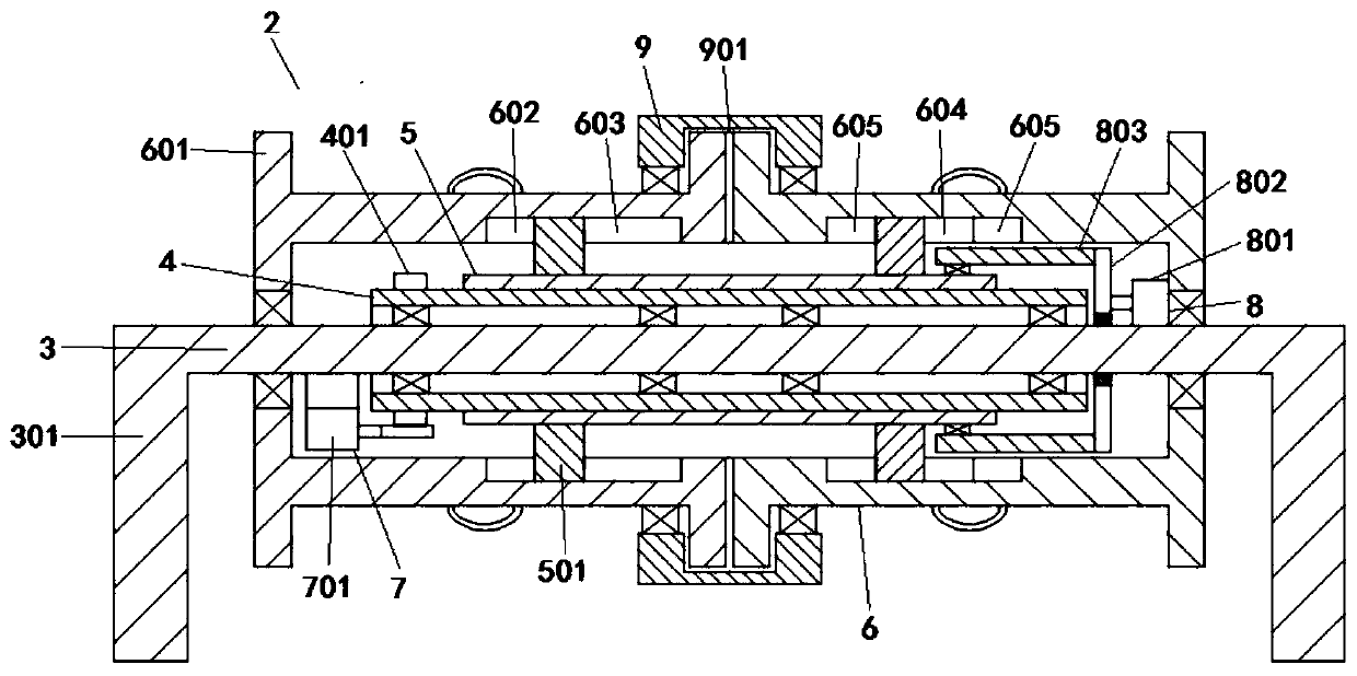
[0004] The purpose of the present invention is to provide a self-winding device for charging piles, which drives the transmission sleeve to rotate through the transmission mechanism, so that the transmission sleeve drives the sliding sleeve to rotate; and the sliding mechanism drives the sliding sleeve to rotate on the side of the transmission sleeve. Sliding up; according to the displacement of the sliding sleeve, the block on the sliding sleeve engages with the first slot or the second annular slot on a rotating sleeve or with the first slots on two rotating sleeves It is snapped together with the second annular groove at the same time, and finally realizes one or two rotating sleeves to drive the cable to rotate and wind in one direction, which solves the problem that the existing charging gun cable cannot be wound and collected, resulting in cable wear and reduced service life of the charging pile. The problem

Method used


Image

  • Self-winding device for charging pile
  • Self-winding device for charging pile

Examples


Embodiment Construction

[0027] The following will clearly and completely describe the technical solutions in the embodiments of the present invention with reference to the accompanying drawings in the embodiments of the present invention. Obviously, the described embodiments are only some, not all, embodiments of the present invention. Based on the embodiments of the present invention, all other embodiments obtained by persons of ordinary skill in the art without creative efforts fall within the protection scope of the present invention.

[0028] In describing the present invention, it is to be understood that the terms "disposed", "open", "bottom", "end", "axial", "length", "inner", "peripheral side", etc. indicate orientation Or positional relationship is only for the convenience of describing the present invention and simplifying the description, but does not indicate or imply that the components or elements referred to must have a specific orientation, be constructed and operated in a specific ori...


PUM


Abstract

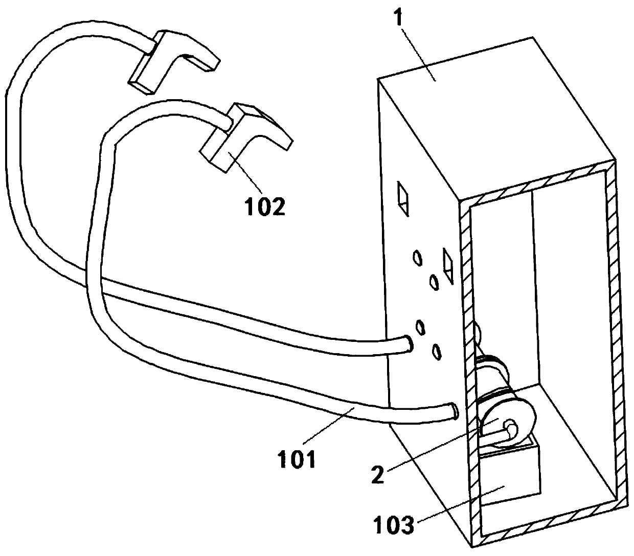
The invention discloses a self-winding device for a charging pile, and relates to the technical field of charging piles. The self-winding device comprises a cabinet, two cables are electrically connected with an inner circuit board of the cabinet, the cables penetrate through the side surface of the cabinet and are electrically connected with a charging gun, a winding device is mounted on the inner wall of the side surface of the cabinet, a cable box is mounted on the inner wall of the bottom surface of the cabinet, the cable box is located below the winding device, and the winding device comprises a connecting shaft, a driving sleeve, a sliding sleeve and a rotating sleeve. According to the self-winding device, the driving sleeve is driven to rotate through a driving mechanism, and the sliding sleeve is driven by a sliding mechanism to slide on the circumferential side face of the driving sleeve, according to the different displacement amounts of the sliding sleeve, so that a clampingblock is in clamped connection with a first clamping groove or second clamping groove, or the first clamping groove and a second annular groove in the rotating sleeve, finally, the fact that one or two rotating sleeves drive the cables to conduct the single-way rotating winding is achieved, automatic single-way winding of the cables can be achieved through the process, the wear of the cables is avoided, and the service life of the charging pile is prolonged.

Description

technical field [0001] The invention belongs to the technical field of charging piles, in particular to a self-winding device for charging piles. Background technique [0002] Electric vehicles have always been regarded as the development trend of the next generation of vehicles. As a "gas station" for electric vehicles, the full development of charging pile construction will undoubtedly provide a huge market. In the three major cities of Beijing, Shanghai and Guangzhou, due to traffic congestion, restrictions on car purchases have been imposed through license plates. [0003] With the popularization of electric vehicles, some existing parking lots will be equipped with charging piles. In order to save resources, most of the charging piles will be equipped with two charging guns; and the cables connected to the charging guns are usually placed in the car after being used by the car owner. The ground, but it is inevitable that there will be water and corrosive substances on...

Claims


Application Information

Patent Timeline
Patent Type & Authority Applications(China)
IPC IPC(8): B65H75/48B65H75/44B60L53/31
CPCB65H75/4481B65H75/48B65H2701/34Y02T10/70Y02T10/7072Y02T90/12
Inventor 杨思伟杨俊
Owner 合肥旺和电子科技有限公司
Why Eureka
Try Eureka