Water retaining device for water turbine main shaft seal

A main shaft sealing and water blocking device technology, applied in mechanical equipment, hydroelectric power generation, engine components, etc., can solve the problems of water and oil mixing, the influence of the operation of the hydraulic turbine unit, long construction period, etc., to achieve easy installation, time saving and The effect of low labor cost and production cost

Pending Publication Date: 2019-08-16
STATE GRID CORP OF CHINA +1
View PDF0 Cites 0 Cited by
  • Summary
  • Abstract
  • Description
  • Claims
  • Application Information

AI Technical Summary

Problems solved by technology

[0002] When the sealing end cover of the main shaft of the turbine fails and the seal is not tight, the water may surge up along the radial direction of the main shaft under the action of centripetal force, and in serious cases may enter the water guide basin, causing water to guide oil and mix water
To solve this problem, the main shaft seal needs to be overhauled, which requires a long construction period and has a great impact on the operation of the turbine unit

Method used


Image

  • Water retaining device for water turbine main shaft seal
  • Water retaining device for water turbine main shaft seal
  • Water retaining device for water turbine main shaft seal

Examples


Embodiment Construction

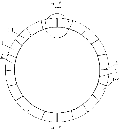
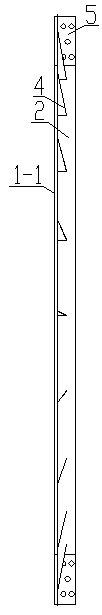
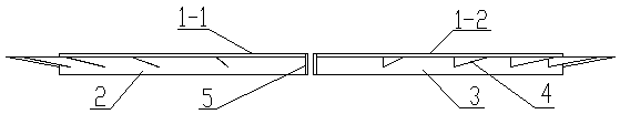
[0020] The present invention will be described in detail below in conjunction with the accompanying drawings and embodiments.

[0021] see figure 1 , figure 2 , image 3 , a hydraulic turbine main shaft seal water retaining device, by the water retaining plate coaming 1, the left water retaining plate gusset 2, the right water retaining plate gusset 3, rib plate 4 and flange 5 constitute. The fender enclosure 1 is a ring split structure, the fender enclosure 1 is composed of the left fender enclosure 1-1 and the right fender enclosure 1-2, the left fender enclosure 1-1 Respectively semi-circular structure with right water retaining plate coaming 1-2, the opening of left water retaining plate coaming 1-1 and right water retaining plate coaming 1-2 is arranged relatively. The edge of the inner circumference of the left fender 1-1 is welded with a semicircular left fender gusset 2, and the edge of the inner circumference of the right fender 1-2 is welded with a semicircular ...


PUM


Abstract

The invention relates to a water retaining device for a water turbine main shaft seal. The water retaining device comprises a water retaining plate coaming, wherein the water retaining plate coaming is of an annular dividing structure; the water retaining plate coaming comprises a left water retaining plate coaming and a right water retaining plate coaming, which are of a semicircular structure; aleft water retaining plate pinch plate and a right water retaining plate pinch plate, which are semicircular, are arranged at edges of peripheral sides in the left water retaining plate coaming and the right water retaining plate coaming respectively; the left water retaining plate pinch plate and the right water retaining plate pinch plate are vertical to the left water retaining plate coaming and the right water retaining plate coaming respectively; a rectangular flange disc is arranged at one side of each of two ends of the left water retaining plate coaming and the right water retaining plate coaming; the flange discs are vertical to the left water retaining plate coaming and the right water retaining plate coaming respectively; and the left water retaining plate coaming and the rightwater retaining plate coaming are fixedly connected through the flange discs. The water retaining device for the water turbine main shaft seal, provided by the invention, is low in production cost and simple to mount; and a condition that main shaft seal water upwells to a water guide oil basin is effectively avoided, the time and the labor cost are saved and a machine set is prevented from beingoperated for long time.

Description

technical field [0001] The invention relates to a water turbine, in particular to a sealing water retaining device for a main shaft of a water turbine. Background technique [0002] When the sealing end cover of the main shaft of the turbine fails and the seal is not tight, the water may surge up along the radial direction of the main shaft under the action of centripetal force, and in serious cases may enter the water guide basin, causing water to guide oil and mix water. To solve this problem, the main shaft seal needs to be overhauled, which requires a long construction period and has a great impact on the operation of the turbine unit. Contents of the invention [0003] The technical problem to be solved by the present invention is to provide a hydraulic turbine main shaft sealing water retaining device, which prevents the main shaft sealing water from rushing into the water guide basin. [0004] The technical scheme that the present invention solves its technical pro...

Claims


Application Information

Patent Timeline
Patent Type & Authority Applications(China)
IPC IPC(8): F03B11/00
CPCF03B11/006Y02E10/20
Inventor 孙永贾巍马锦彪
Owner STATE GRID CORP OF CHINA
Why Eureka
Try Eureka