

Rolling type sliding vane pump rotor
A technology of sliding vane pump and rolling type, applied in the direction of rotary piston pump, rotary piston type/oscillating piston type pump components, pumps, etc., can solve the problems of high bearing, short service life of shaft and bearing, slow surface wear, etc. , to achieve the effect of avoiding volume loss, avoiding medium leakage and reducing volume loss
- Summary
- Abstract
- Description
- Claims
- Application Information
AI Technical Summary
Problems solved by technology
Method used
Image

Examples
Embodiment Construction
[0025] The present invention will be further described in detail below in conjunction with the accompanying drawings and embodiments.
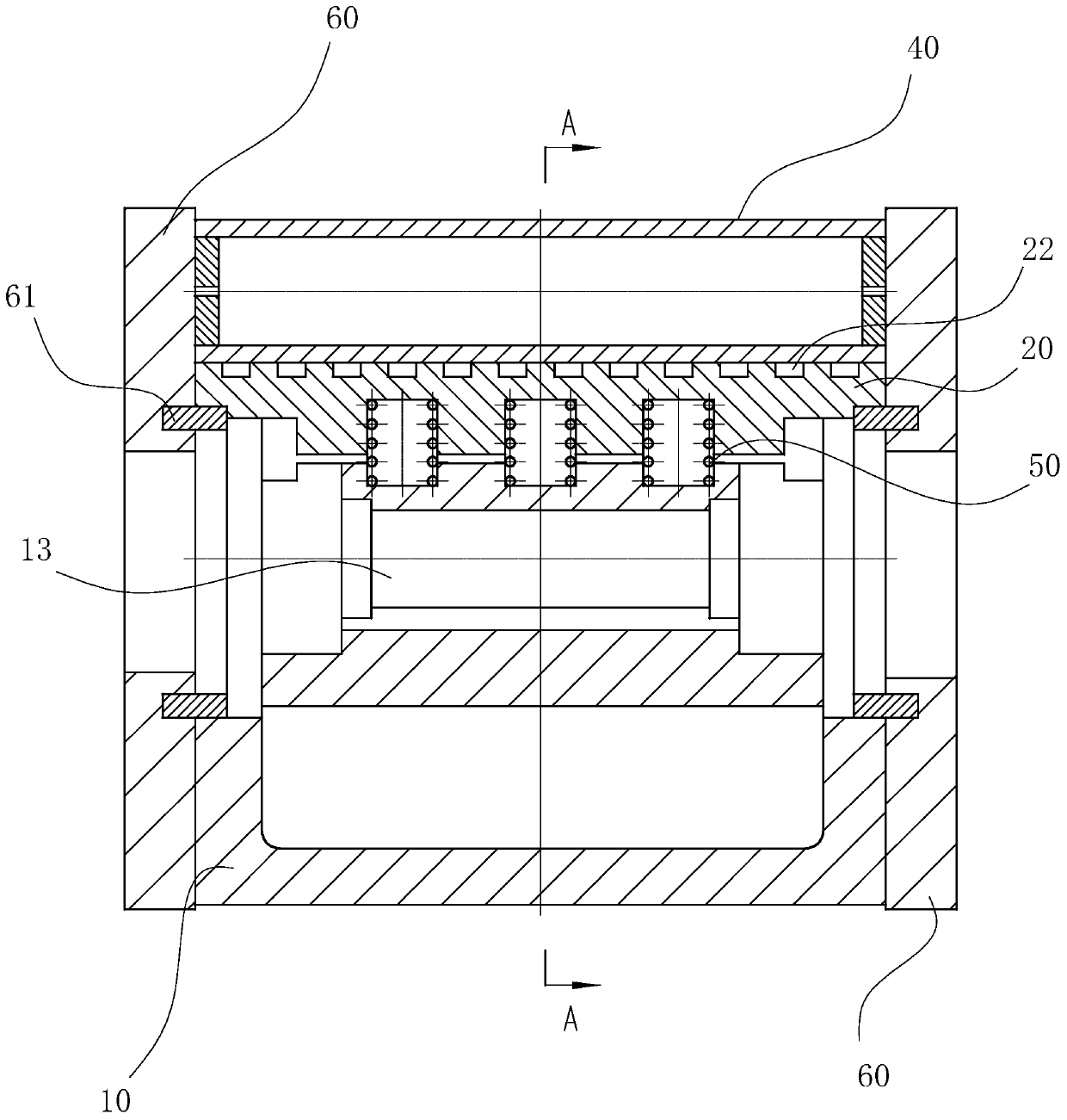
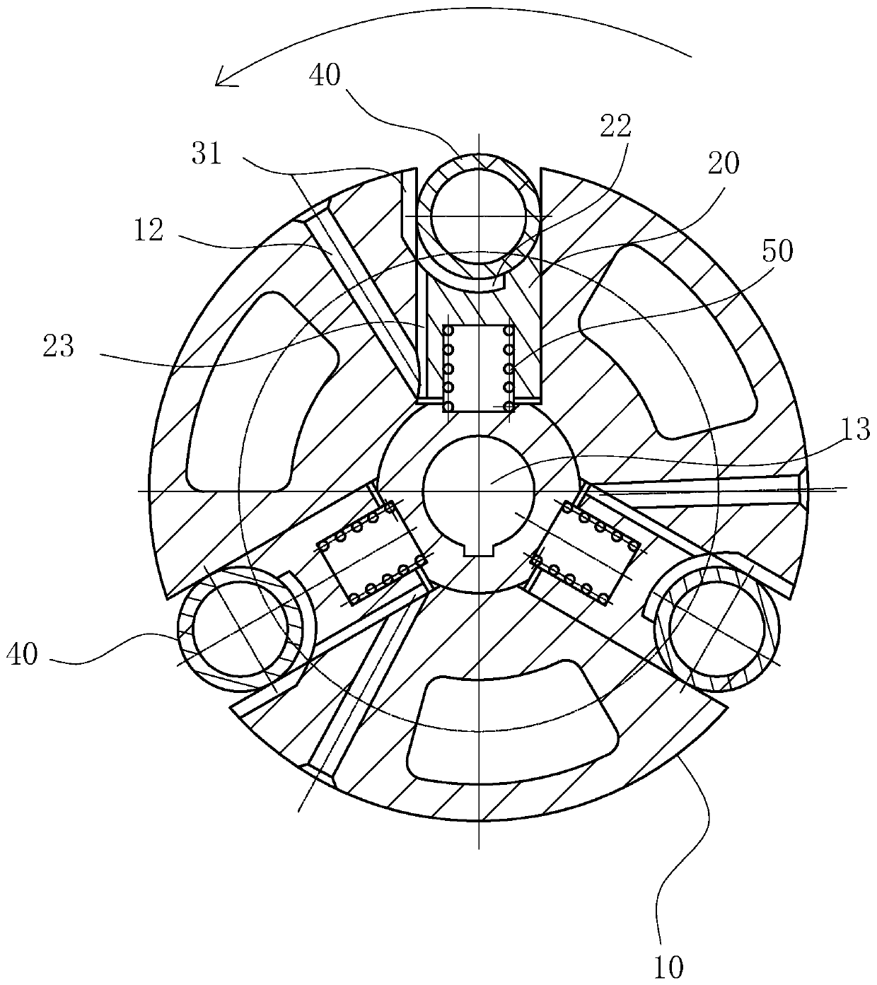
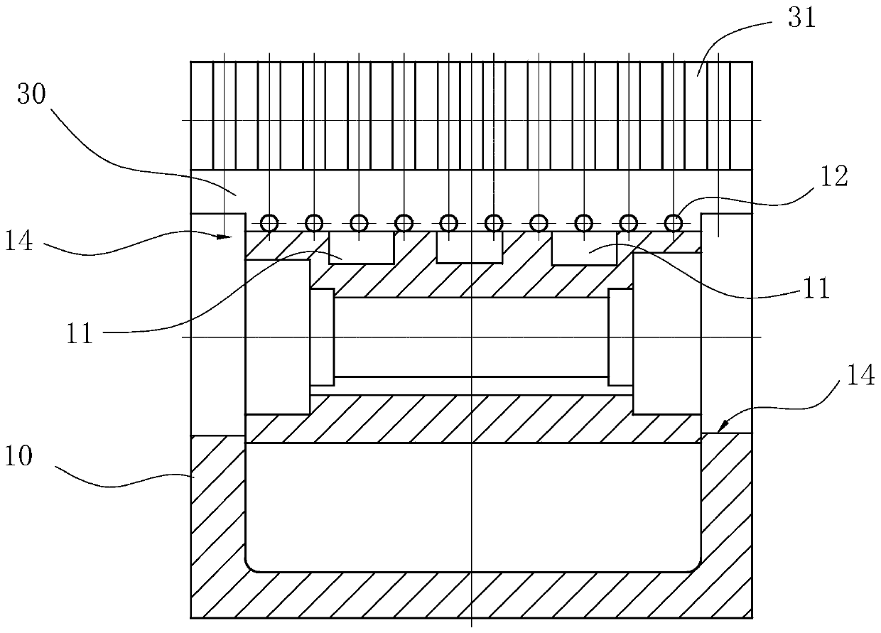
[0026] see figure 1- Fig. 9, the rotor of the rolling vane pump includes a rotor body 10, a vane body 20 and a roller 40, the rotor body 10 is provided with a plurality of sliding grooves 30 along its circumference, and there are a plurality of vane bodies 20, each The slider bodies 20 are all radially slidably arranged in the corresponding sliding grooves 30, and there are also a plurality of rollers 40 corresponding to each slider body 20 respectively. Specifically, each roller 40 is rotatably fit on the top of each slider body 20, wherein the top of the slider body 20 is provided with an arc-shaped roller groove 21 for placing the roller 40 and capable of making sealing contact with the outer circle of the roller 40, in this embodiment Among them, the size of the arc-shaped roller groove 21 matches the size of the roller 40, so that the ro...
PUM
 Abstract
Description
Claims
Application Information