Automatic detection equipment for circle run-out of rim

An automatic detection and circular beating technology, which is applied in the direction of measuring devices, mechanical measuring devices, instruments, etc., can solve the problems of inappropriate positioning, affecting detection accuracy, and low efficiency, so as to improve handling efficiency, improve detection accuracy, and avoid secondary problems. The effect of secondary errors

Pending Publication Date: 2019-08-16
ZHEJIANG WANFENG MOTORCYCLE WHEEL
View PDF0 Cites 10 Cited by
  • Summary
  • Abstract
  • Description
  • Claims
  • Application Information

AI Technical Summary

Problems solved by technology

[0004] 1. At present, the end circular runout and radial circular runout of the rim are generally divided into two processes for detection, so it needs to be transferred and transported. If manual handling is used, it will consume a lot of manpower and be inefficient, resulting in low detection efficiency for the circular runout of the rim ;
[0005] 2. The wheel hub is divided into the flower space product and the shaft hole product. At present, the round runout of the end of the wheel rim is measured. Before the measurement, the key on the drive shaft and the keyway on the wheel hub are used to position the wheel hub, and this positioning fit is not applicable to the wheel hub. shaft hole products;
[0006] 3. The existing device for detecting circular runout is only suitable for the same type of wheel hub. Because the position and size of the positioning holes are different for different types of hubs, when the wheel hub model is changed, a different wheel hub positioning device needs to be replaced, resulting in The detection device has limitations, not only is it inefficient, but also causes secondary errors due to multiple replacements, which affects the detection accuracy

Method used


Image

  • Automatic detection equipment for circle run-out of rim
  • Automatic detection equipment for circle run-out of rim
  • Automatic detection equipment for circle run-out of rim

Examples


Embodiment Construction

[0031] The present invention will be further described below in conjunction with the accompanying drawings.

[0032] In the description of the present invention, it should be understood that the terms "upper", "lower", "forward", "backward", "surface", "side", "inner", "surrounding" and the like indicate an orientation or The positional relationship is only for the convenience of describing the present invention and simplifying the description, but does not indicate or imply that the components or elements referred to must have a specific orientation, be constructed and operated in a specific orientation, and thus should not be construed as limiting the present invention.

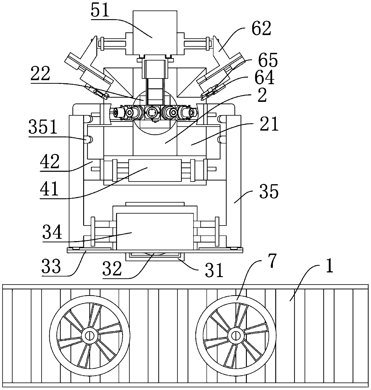
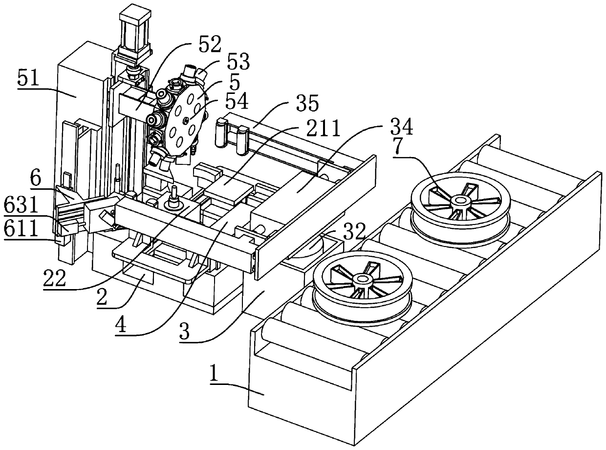
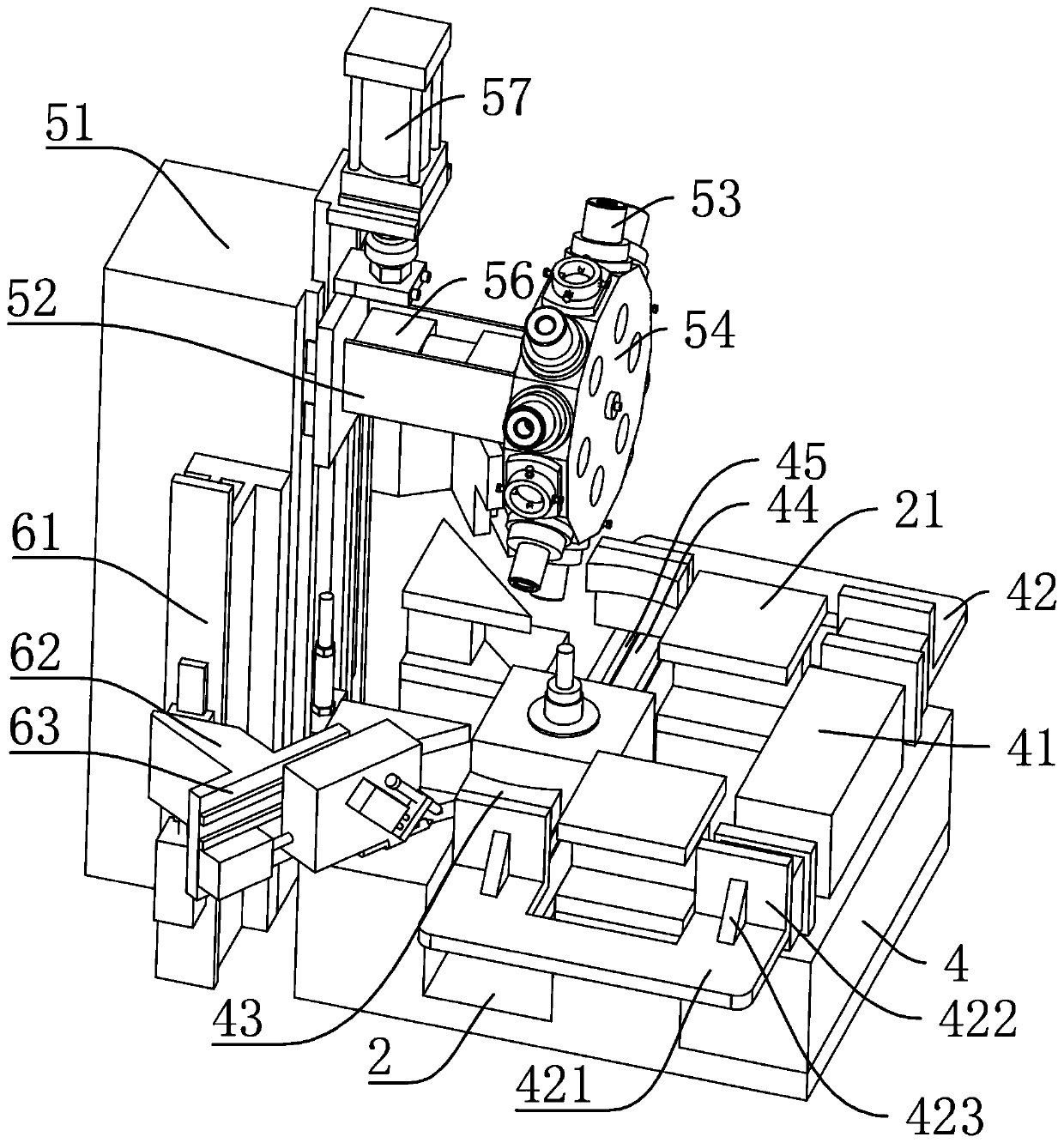
[0033] Such as Figure 1-8 As shown, an automatic detection device for wheel rim runout, including a transportation device 1 for transporting the wheel hub 7, a workbench 2 for placing the wheel hub 7, a handling device 3 for transporting the wheel hub 7 to the workbench 2, and a clamping device for clampin...


PUM


Abstract

The invention discloses automatic detection equipment for circle run-out of a rim. The automatic detection equipment comprises a transportation device for transporting a hub, a workbench for placing the hub, a carrying device for carrying the hub to the workbench, a clamping device for clamping the hub, a positioning device for positioning the hub and a detection device for detecting end part circle run-out and radial circle run-out of the rim; the positioning device comprises a positioning wheel; a positioning shaft has a plurality of types, and the inner end of the positioning shaft is mounted on the positioning wheel through bearings; a positioning boss is arranged at one end of the positioning shaft, and a transmission hole is formed in the other end of the positioning shaft; the transmission hole is matched with a transmission shaft for transmission; a plurality of adjusting seats are arranged on the side wall of the positioning wheel; four groups of jackscrews are uniformly distributed on the side wall of the adjusting seats, and fixed nuts are arranged on the jackscrews; a driving motor is arranged in a positioning box; a positioning air cylinder is fixedly connected to theupper end of a stand column; and end part circle run-out and radial circle run-out of the rim can be simultaneously detected, and the equipment can adapt to hubs of different types and sizes and is relatively high in detection precision.

Description

technical field [0001] The invention relates to detection equipment, in particular to an automatic detection equipment for wheel rim runout. Background technique [0002] During the use of motorcycle aluminum alloy wheels, the reliability of braking is directly related to the comfort and safety of driving. The brake ring runout value is one of the important indicators. According to the current processing technology and method, the important factors affecting the runout of the brake ring include the runout value of the rim end face of the hub and the radial runout value of the rim. [0003] At present, the circular runout detection of the rim has the following shortcomings: [0004] 1. At present, the end circular runout and radial circular runout of the rim are generally divided into two processes for detection, so it needs to be transferred and transported. If manual handling is used, it will consume a lot of manpower and be inefficient, resulting in low detection efficie...

Claims


Application Information

Patent Timeline
Patent Type & Authority Applications(China)
IPC IPC(8): G01B21/00
CPCG01B5/0002G01B5/0025G01B21/00
Inventor 吕允刚姚玉兰吴旭定王锦文盛林江朱贤忠
Owner ZHEJIANG WANFENG MOTORCYCLE WHEEL
Why Eureka
Try Eureka