
Steam turbine main shaft vibration monitoring system

A vibration monitoring system and steam turbine technology, applied in engine testing, mechanical component testing, machine/structural component testing, etc., can solve problems such as lack of protection for signal lines and difficult reliable monitoring of steam turbine operating status

Inactive Publication Date: 2019-08-16
内蒙古君正能源化工集团股份有限公司
View PDF6 Cites 2 Cited by
  • Summary
  • Abstract
  • Description
  • Claims
  • Application Information

AI Technical Summary

Problems solved by technology

[0006] The purpose of the present invention is to solve the problem that the signal lines of various sensors used to detect the operating conditions of the main shaft in the bearing housing of the current steam turbine lack protection, so that it is difficult to implement reliable monitoring of the operating state of the steam turbine. Therefore, a vibration of the main shaft of the steam turbine is provided. Monitoring System

Method used


Image

  • Steam turbine main shaft vibration monitoring system
  • Steam turbine main shaft vibration monitoring system

Examples


Embodiment Construction

[0029] In order to make the purpose, technical solutions and advantages of the embodiments of the present invention clearer, the technical solutions in the embodiments of the present invention will be clearly and completely described below in conjunction with the drawings in the embodiments of the present invention. Obviously, the described embodiments It is a part of embodiments of the present invention, but not all embodiments. Based on the embodiments of the present invention, all other embodiments obtained by persons of ordinary skill in the art without creative efforts fall within the protection scope of the present invention.

[0030] In the description of the present invention, it should be noted that unless otherwise specified and limited, the terms "installation", "connection" and "connection" should be understood in a broad sense, for example, it can be a fixed connection or a detachable connection. Connected, or integrally connected; it may be mechanically connected...


PUM


Abstract

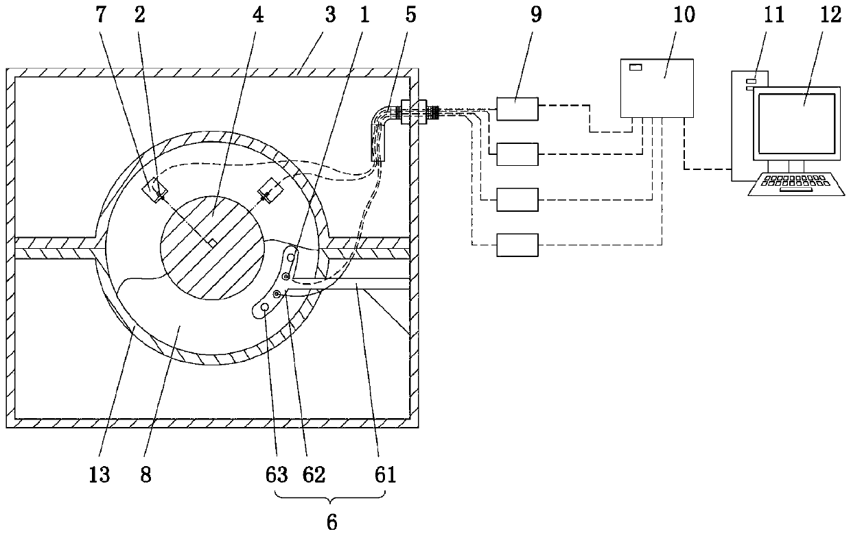
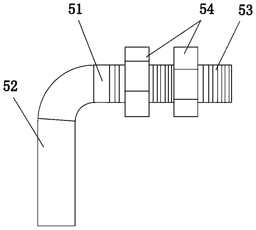
The invention relates to the technical field of steam turbine safety operation monitoring, and provides a steam turbine main shaft vibration monitoring system. The system comprises a first sensor usedfor detecting an axial movement of a main shaft of a steam turbine, a second sensor used for detecting a radial movement of the main shaft of the steam turbine, and a steam turbine remote monitoringdevice, wherein the first sensor and the second sensor are arranged on one side of the main shaft in a bearing box of the steam turbine; a bent threading pipe is mounted on a side wall of the bearingbox; and signal lines of the first sensor and the second sensor are led out of the threading pipe and are connected with the steam turbine remote monitoring device. By designing the bent threading pipe, the signal lines of the first sensor and the second sensor are effectively isolated for protection; the phenomenon that the bearing box leaks oil because the lubricating oil jet in the bearing boxflows out along outgoing lines of the sensors is avoided; and remote monitoring of the axial and radial movements of the main shaft of the steam turbine is ensured.

Description

technical field [0001] The invention relates to the technical field of monitoring the safe operation of steam turbines, in particular to a vibration monitoring system for a main shaft of a steam turbine. Background technique [0002] The operating condition of the main shaft of the steam turbine is a key indicator of the safe and stable operation of the steam turbine. At present, multiple sensors are usually used in the bearing box of the steam turbine to detect parameters such as the speed, eccentricity, shaft vibration, and differential expansion of the main shaft of the steam turbine. After the signal lines of these sensors are drawn out of the bearing box of the steam turbine, they pass The monitoring system is connected, and the remote monitoring system reads and stores relevant detection data in real time, and displays them online in real time, so that the staff can intuitively observe the safe operation status of the steam turbine. [0003] A bearing seat is arranged...

Claims


Application Information

Patent Timeline
IPC IPC(8): G01M15/00G01M15/02G01M13/00
CPCG01M13/00G01M15/00G01M15/02
Inventor 马庭龙秦佳伟高飞于丰收李强孙向军贾军
Owner 内蒙古君正能源化工集团股份有限公司
Learn More